Cutaway view by the renowned graphic illustrator John Barrett at Navy Yard Associates.
| |
| |||
| U.S.S. Allen M. Sumner DD-692 | ||||
| Shipyard Plans Cutaway view by the renowned graphic illustrator John Barrett at Navy Yard Associates. | ||||
The Preliminary Designs
Bureau of Ships' "Spring
Styles" Book # 3 (1939-1944)
Termed "Spring Styles" by the Preliminary
Design staff (after ladies' fashion catalogs), these drawings were an important
part of the development of the design of the Allen M. Sumner class. The
"Spring Styles" plans usually represent only some of the options
presented to the General Board, with the others existing only in tabular form.
They also do not often represent final designs, which were developed in detail
following approval of basic characteristics and were frequently changed in the
process.
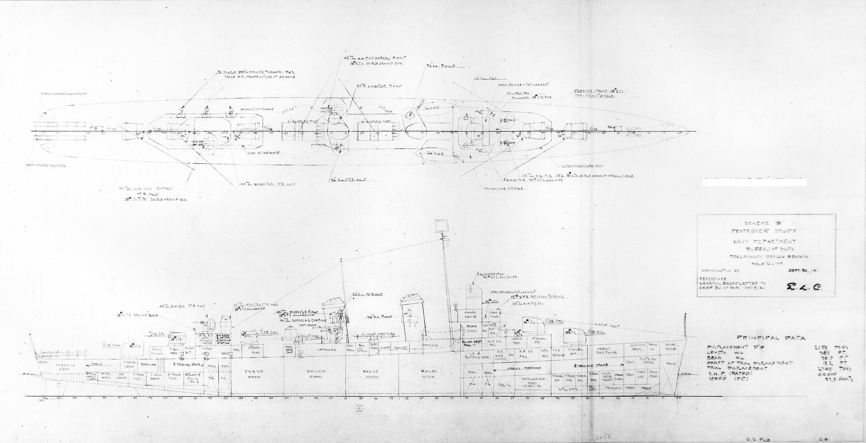
Scheme "B"
Preliminary design plan prepared for the General Board as part of the
process leading to the Allen M. Sumner (DD-692) class design.
This 30 September 1941 plan, for a 2150-ton (standard displacement) ship,
provides a slightly updated Fletcher (DD-445) class destroyer, retaining
its five single 5"/38 gun mounts (although two are semi-open mounts) and
ten torpedo tubes. Among notable changes are a modified bridge arrangement and
two twin 40mm anti-aircraft gun mounts (in place of the single quad 1.1"
weapon of the original Fletchers). Naval Historical Center Photo #:
S-511-51-G.
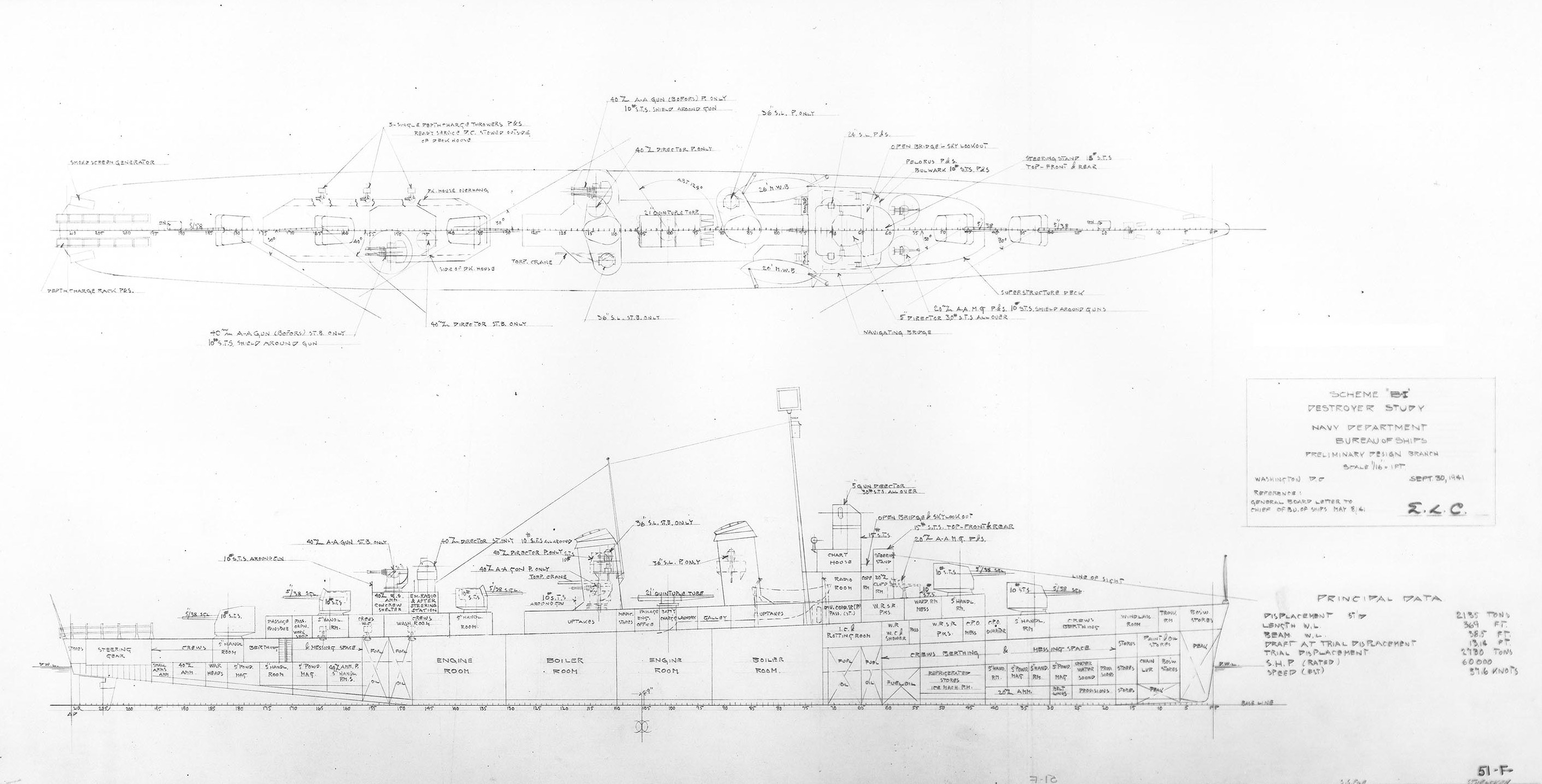
Scheme "B-I"
Preliminary design plan prepared for the General Board as part of the
process leading to the Allen M. Sumner (DD-692) class design.
This 30 September 1941 plan, for a 2135-ton (standard displacement) ship,
provides a slightly updated Fletcher (DD-445) class destroyer, retaining
its five single 5"/38 gun mounts (two of which are semi-open mounts) but
eliminating one bank of five torpedo tubes to achieve a less crowding amidships.
Other notable changes are a modified bridge arrangement and two twin 40mm
anti-aircraft gun mounts (in place of the single quad 1.1" weapon of the
original Fletchers). Naval Historical Center Photo #: S-511-51-F.
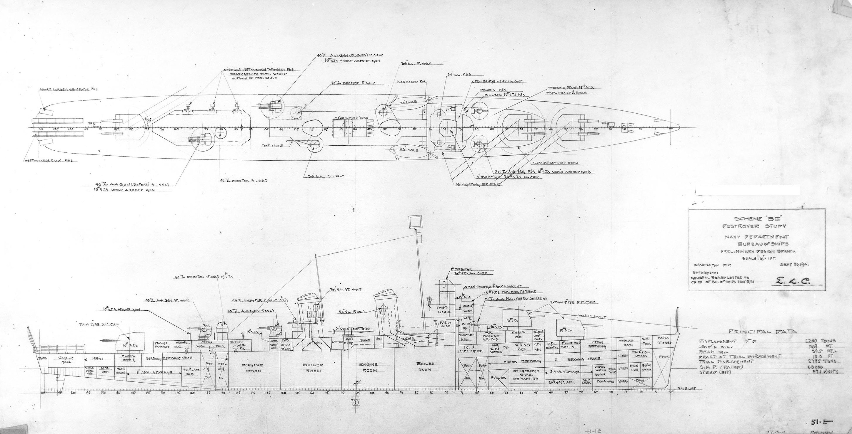
Scheme "B-II"
Preliminary design plan prepared for the General Board as part of the process
leading to the Allen M. Sumner (DD-692) class design.
This 30 September 1941 plan, for a 2200-ton (standard displacement) ship,
introduces the twin 5"/38 dual-purpose gun mount as a destroyer weapon.
Three of these are provided, as well as two twin 40mm anti-aircraft guns and a
single bank of five torpedo tubes, giving a less crowded arrangement amidships.
Further developed as Scheme "B-VII" of 10 March 1942, this became the
basic DD-692 design. Naval Historical Center Photo #: S-511-51-E.
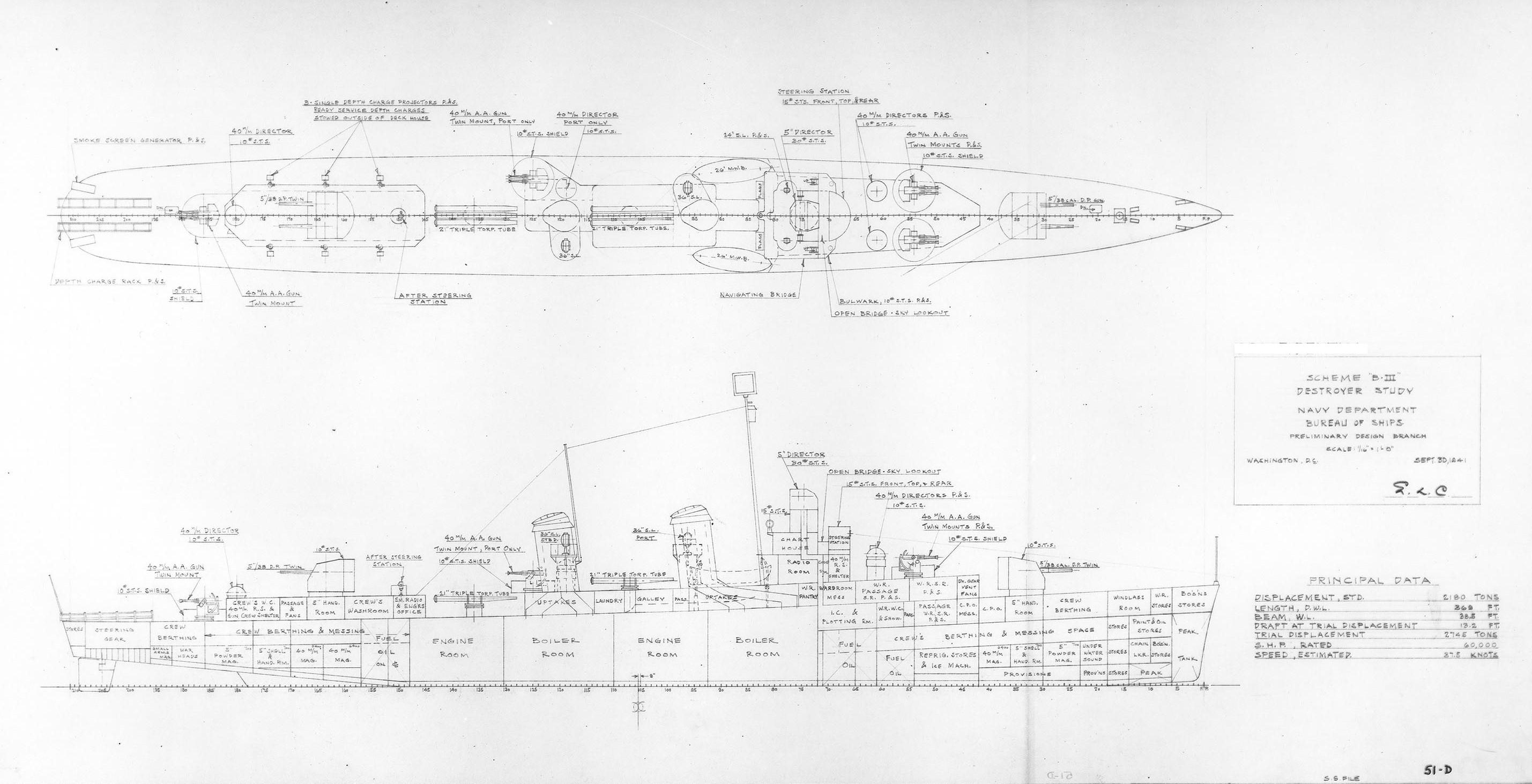
Scheme "B-III"
Preliminary design plan prepared for the General Board as part of the
process leading to the Allen M. Sumner (DD-692) class design.
This 30 September 1941 plan, for a 2180-ton (standard displacement) ship,
provides two twin 5"/38 dual-purpose gun mounts (one forward and one atop
the after deck house), four twin 40mm anti-aircraft guns, and two triple torpedo
tube mountings. Naval Historical Center Photo #: S-511-51-D.
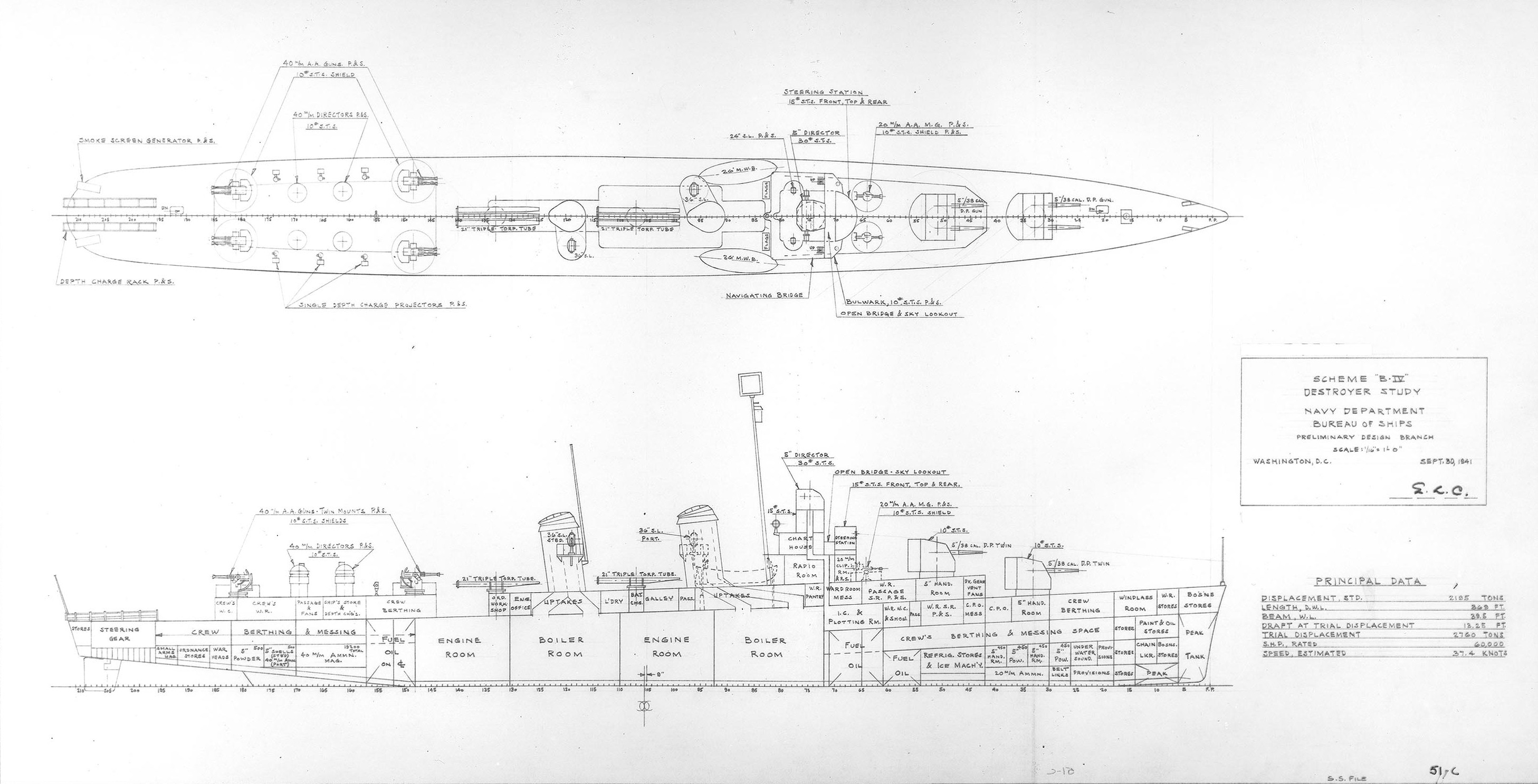
Scheme "B-IV"
Preliminary design plan prepared for the General Board as part of the
process leading to the Allen M. Sumner (DD-692) class design.
This 30 September 1941 plan, for a 2195-ton (standard displacement) ship,
provides two twin 5"/38 dual-purpose gun mounts forward, four twin 40mm
anti-aircraft guns on the corners of a large after deckhouse, and two triple
torpedo tube mountings. Naval Historical Center Photo #: S-511-51-C.
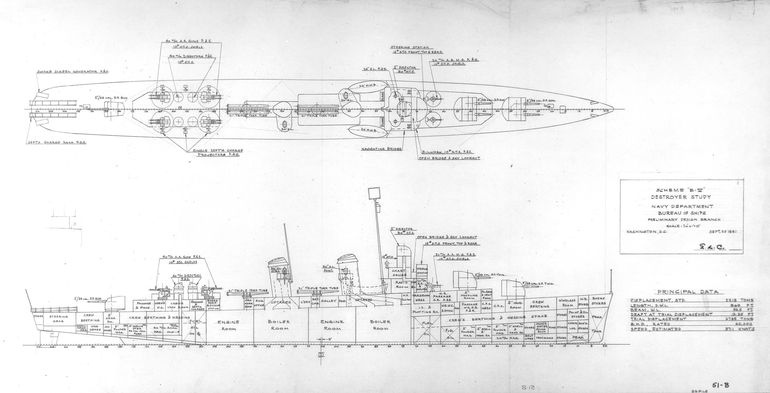
Scheme "B-V"
Preliminary design plan prepared for the General Board as part of the
process leading to the Allen M. Sumner (DD-692) class design.
This 30 September 1941 plan, for a 2215-ton (standard displacement) ship,
provides two twin 5"/38 dual-purpose gun mounts forward and a single
5"/38 dual-purpose gun mount aft, four twin 40mm anti-aircraft guns on the
after deckhouse, and two triple torpedo tube mountings. Naval Historical Center
Photo #: S-511-51-B.
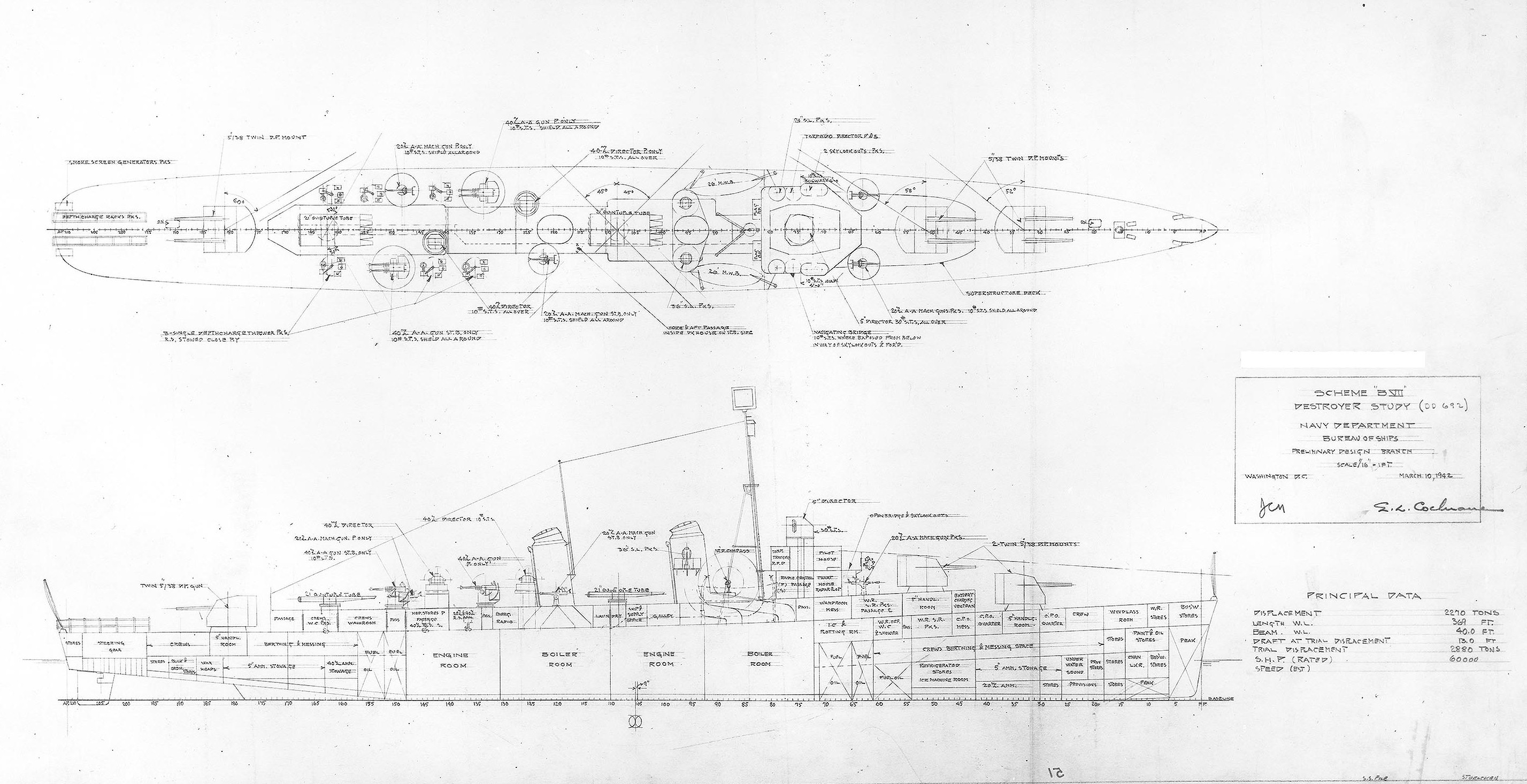
Scheme "B-VII"
Preliminary design plan prepared for the General Board near the end of the
process leading to the Allen M. Sumner (DD-692) class design.
This 10 March 1942 plan, for a 2270-ton (standard displacement) ship, is a
development of Scheme "B-II" of 30 September 1941, and was the basis
for the DD-692 class design. It provides three twin 5"/38 dual-purpose gun
mounts (two forward, one aft), two twin 40mm anti-aircraft gun mounts, and ten
torpedo tubes in two banks of five. Note that the bridge arrangement has been
altered from the earlier schemes in the Scheme "B" series. Naval
Historical Center Photo #: S-511-51.
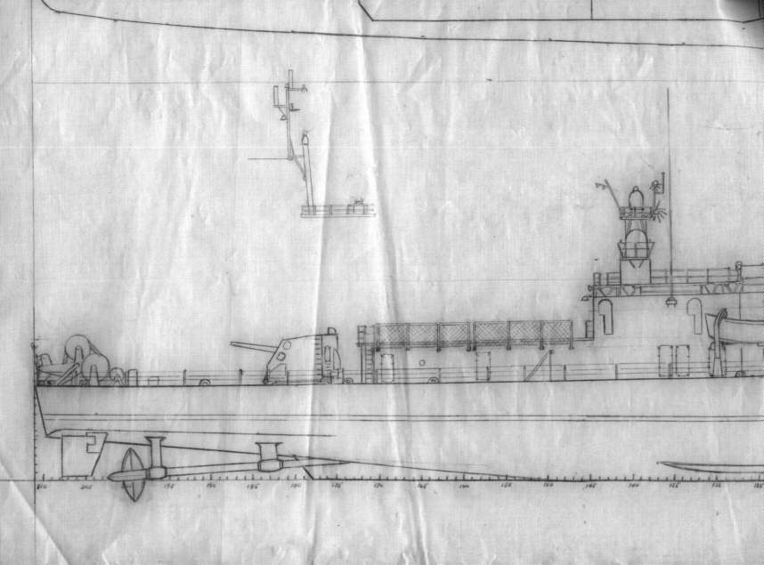
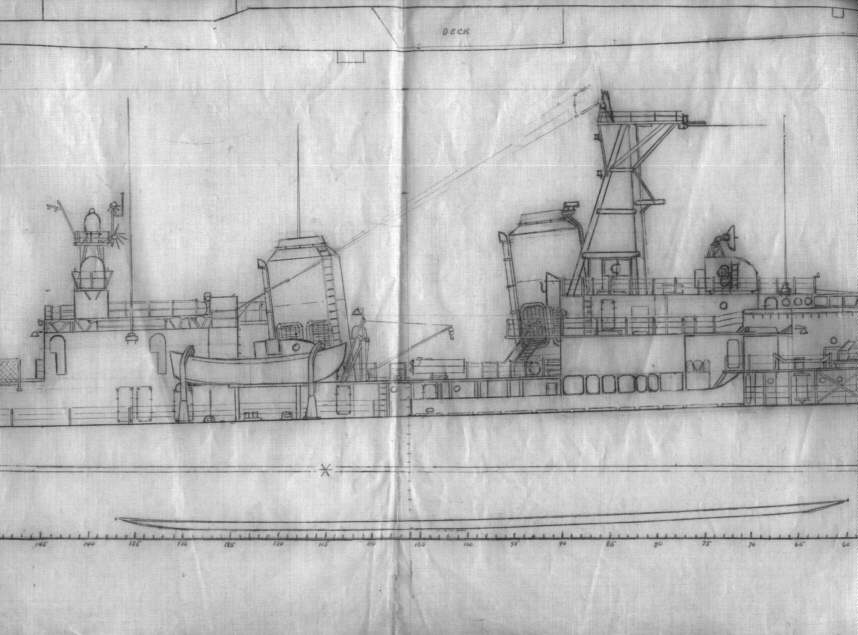
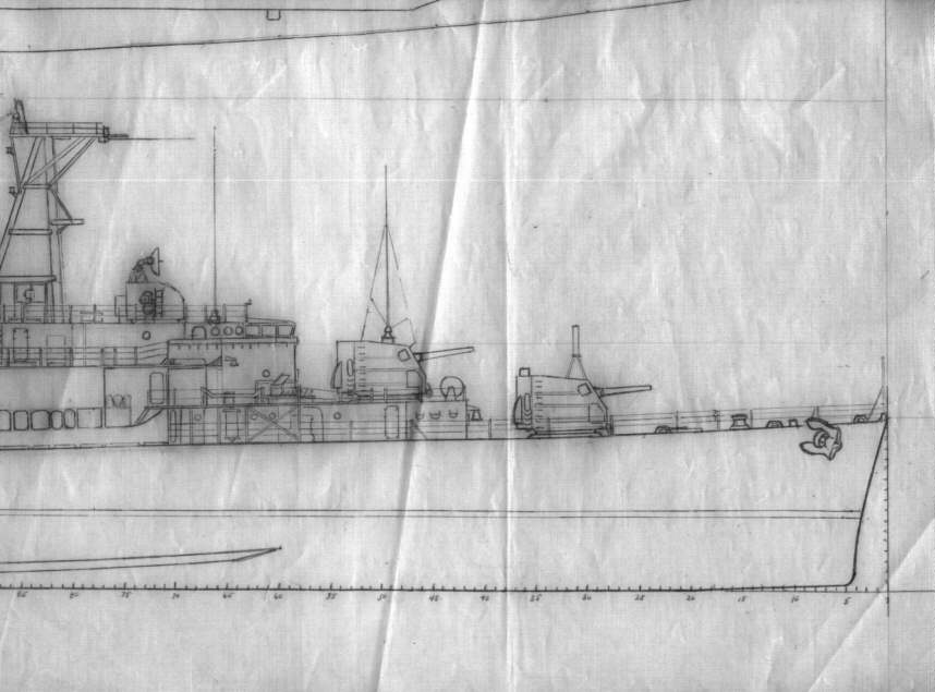
1943 Outboard Profile
Gibbs & Cox - July 7, 1943
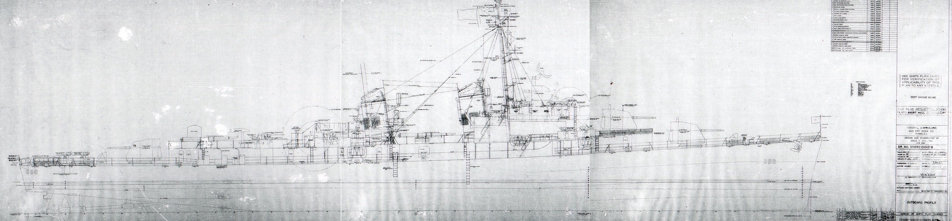
This plan was completed the day the Keel was laid for the Sumner at Federal Shipbuilding. Many thanks to Ed Zajkowski for sending us this rare document.
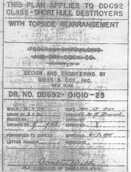
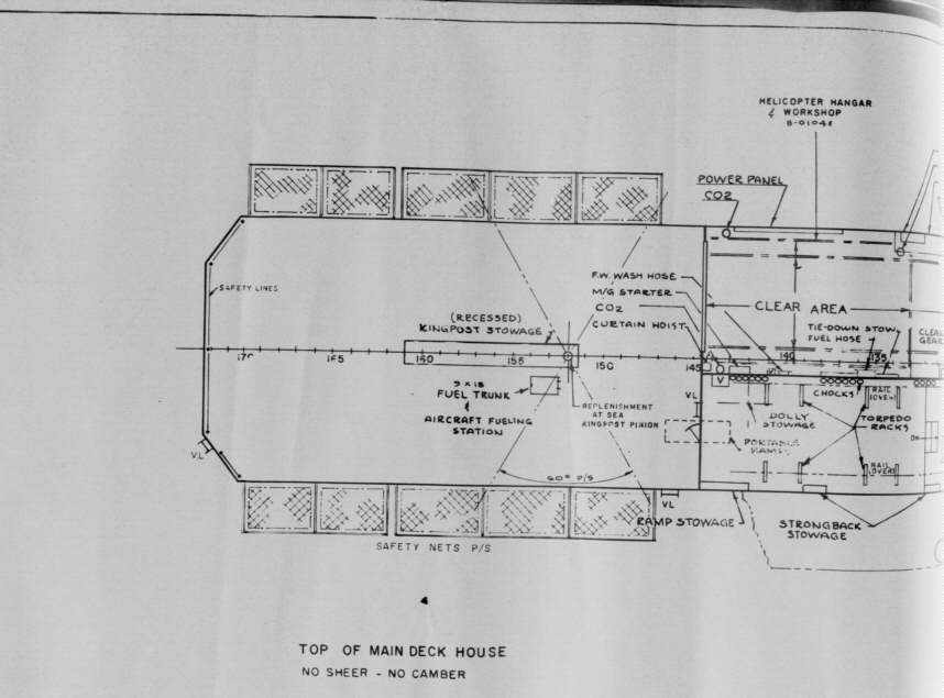
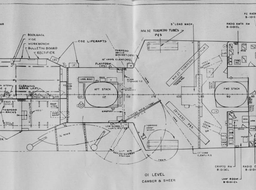
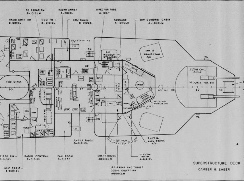
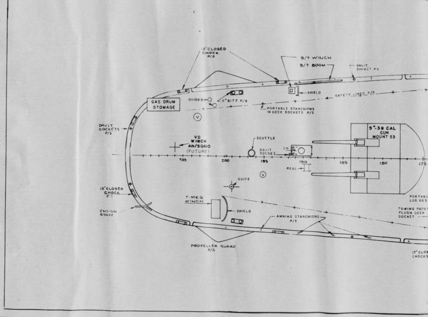
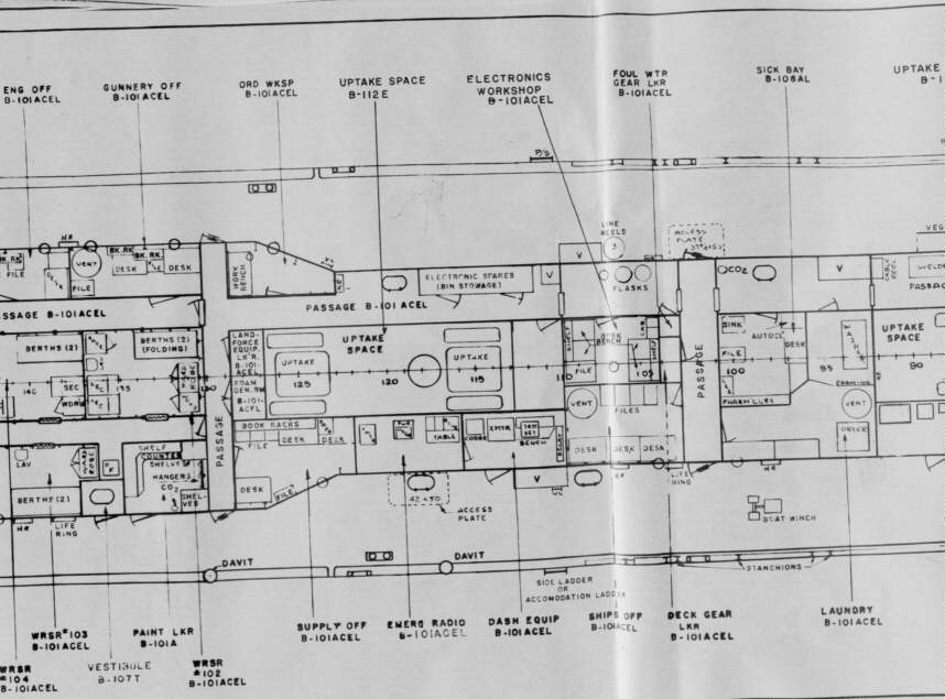
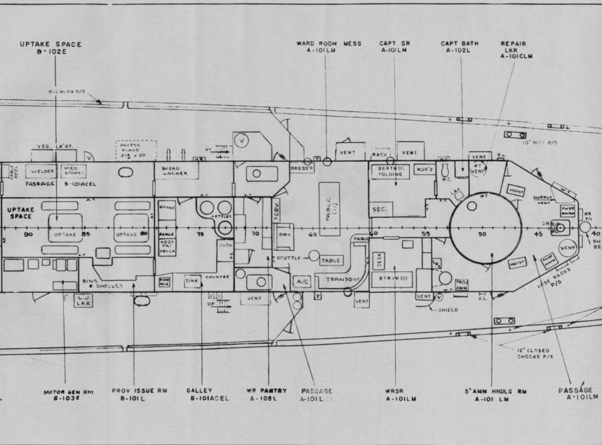
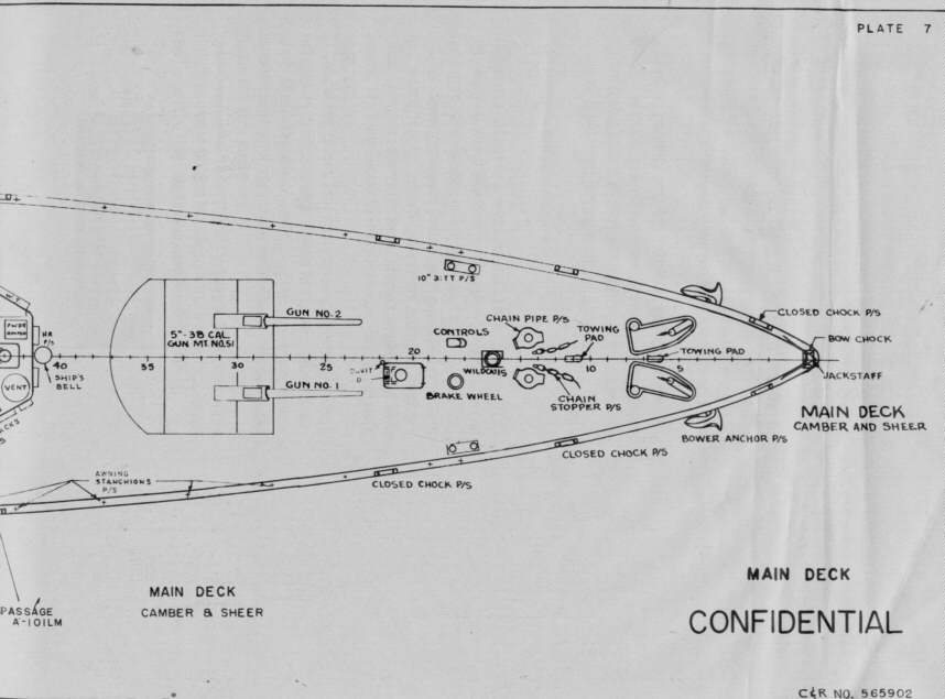
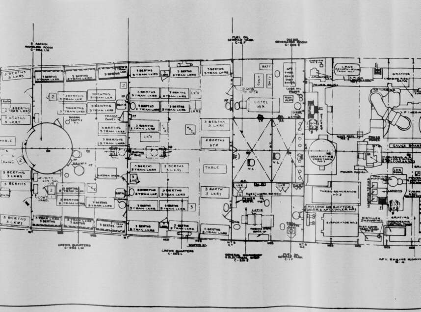
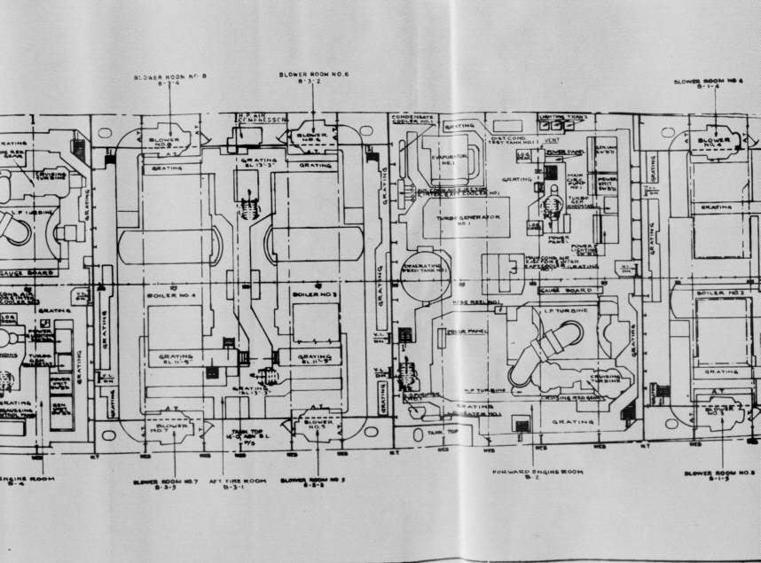
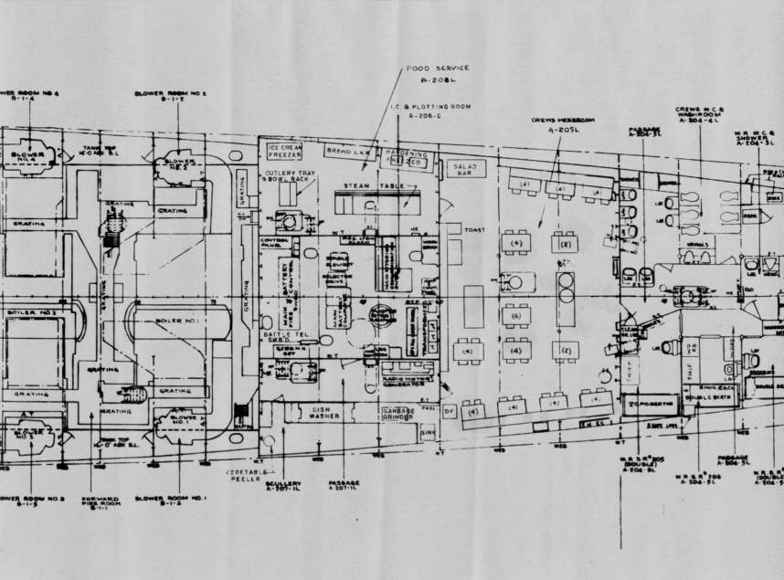
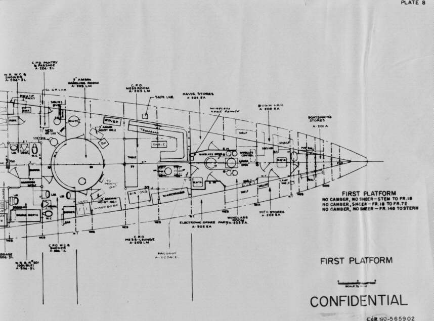
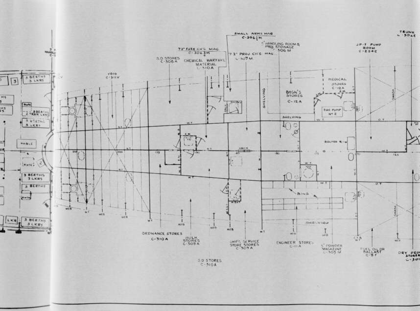
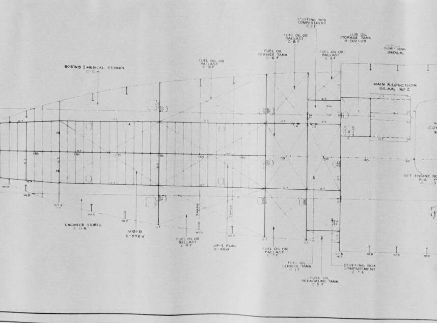
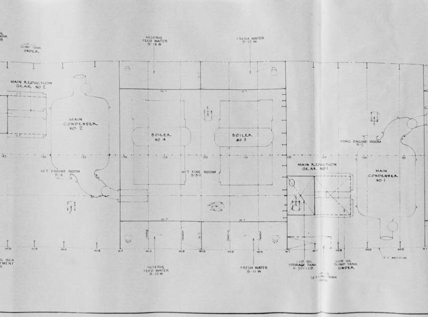
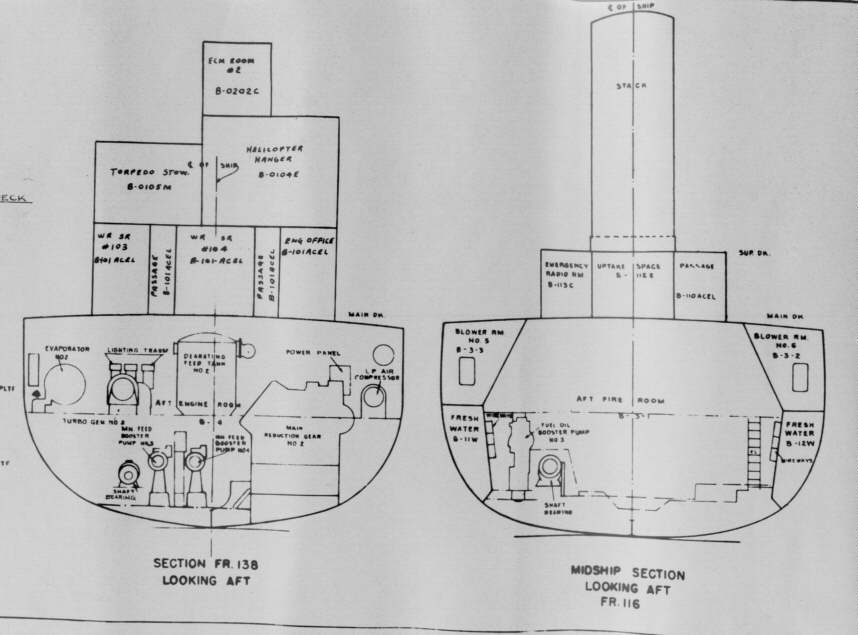
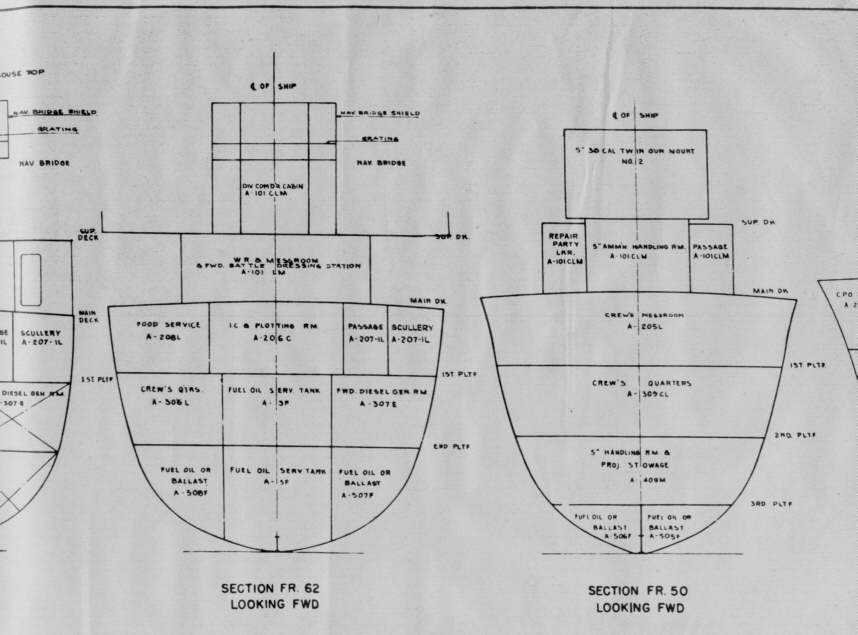
1944 Deck Supports
& Compartment & Access - Inboard Profile
Gibbs & Cox - May 27, 1944
Click on the portion of the ship you wish to review and the
relevant section of the Plan will be displayed
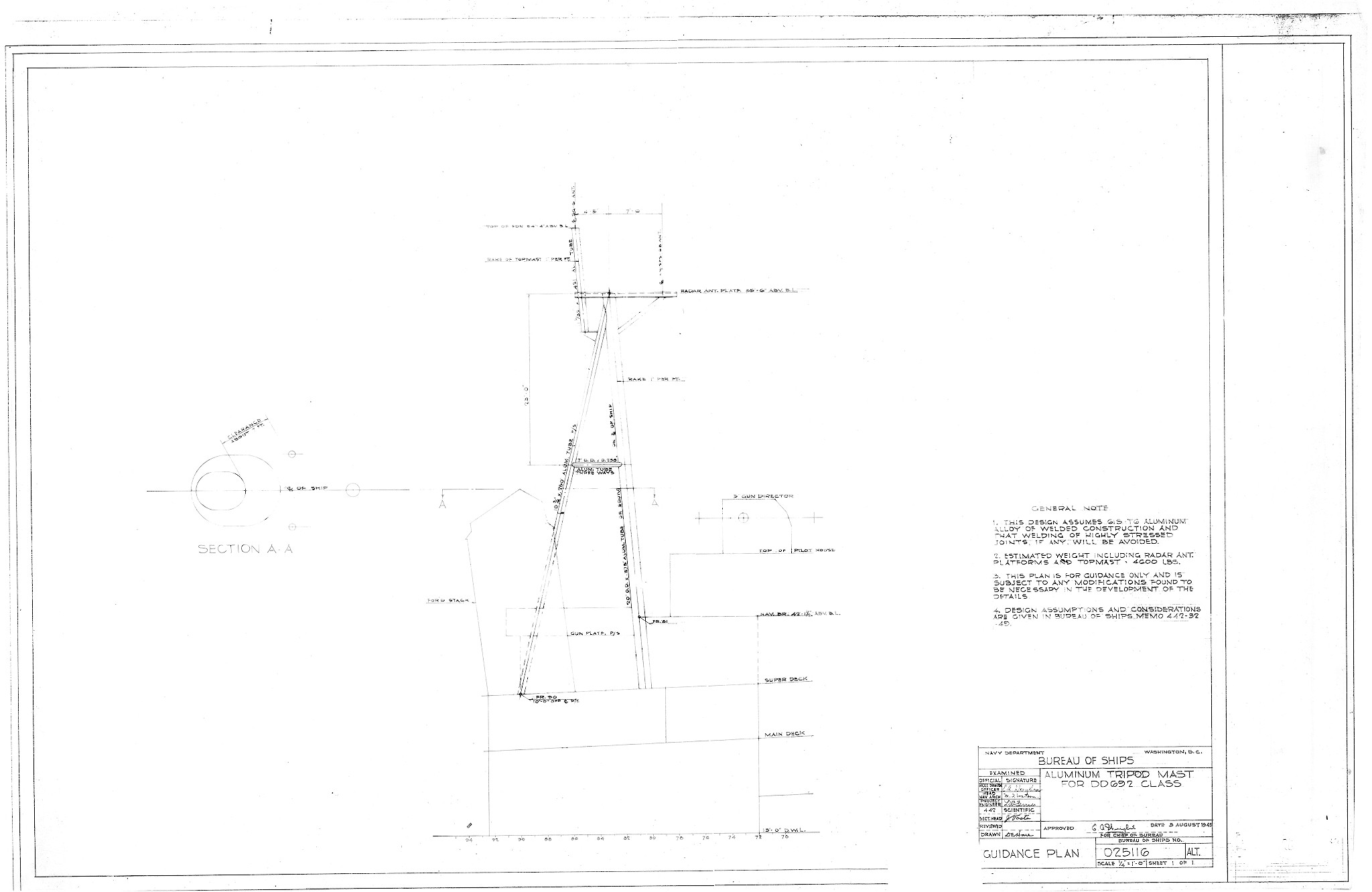
1945 DD-692 Class
Aluminum Tripod Mast
BuShips - August 3, 1945
1947 DD-692 Class Long
Hull - Hunter Killer (Proposed)
BuShips - August 20, 1947
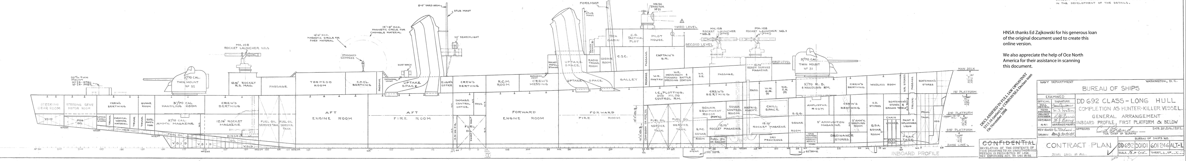
This is a large image, note the main armament would have
been 3"/70s and MK108 Rocket Launchers.
To see more of this set of plans go to the Historic
Naval Ships website
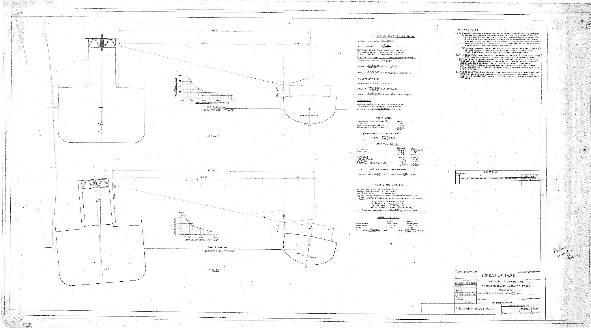
Plan for the loading calculations of an at sea transfer
between
the Hunter Killer and an AE
 |
 |
 |
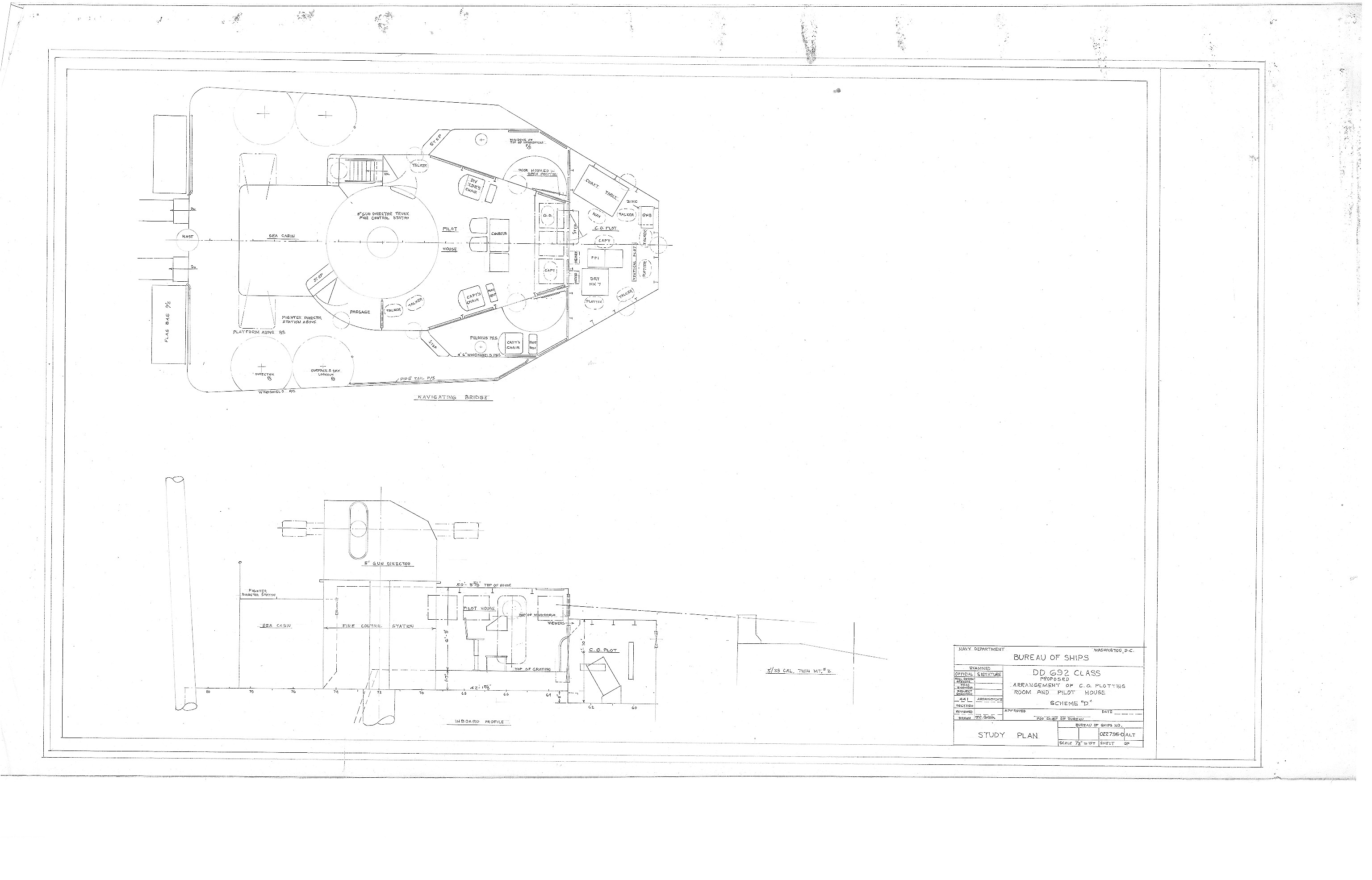 |
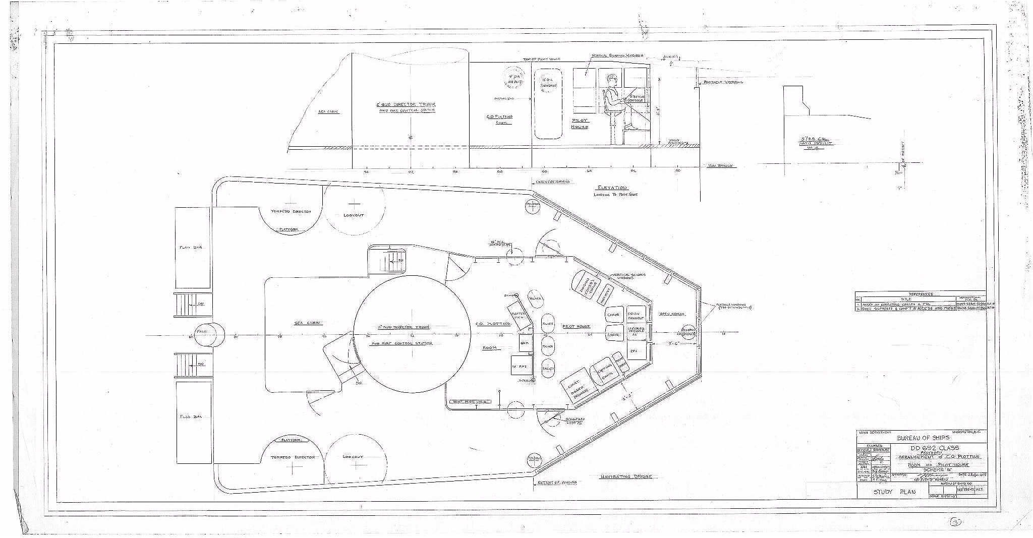
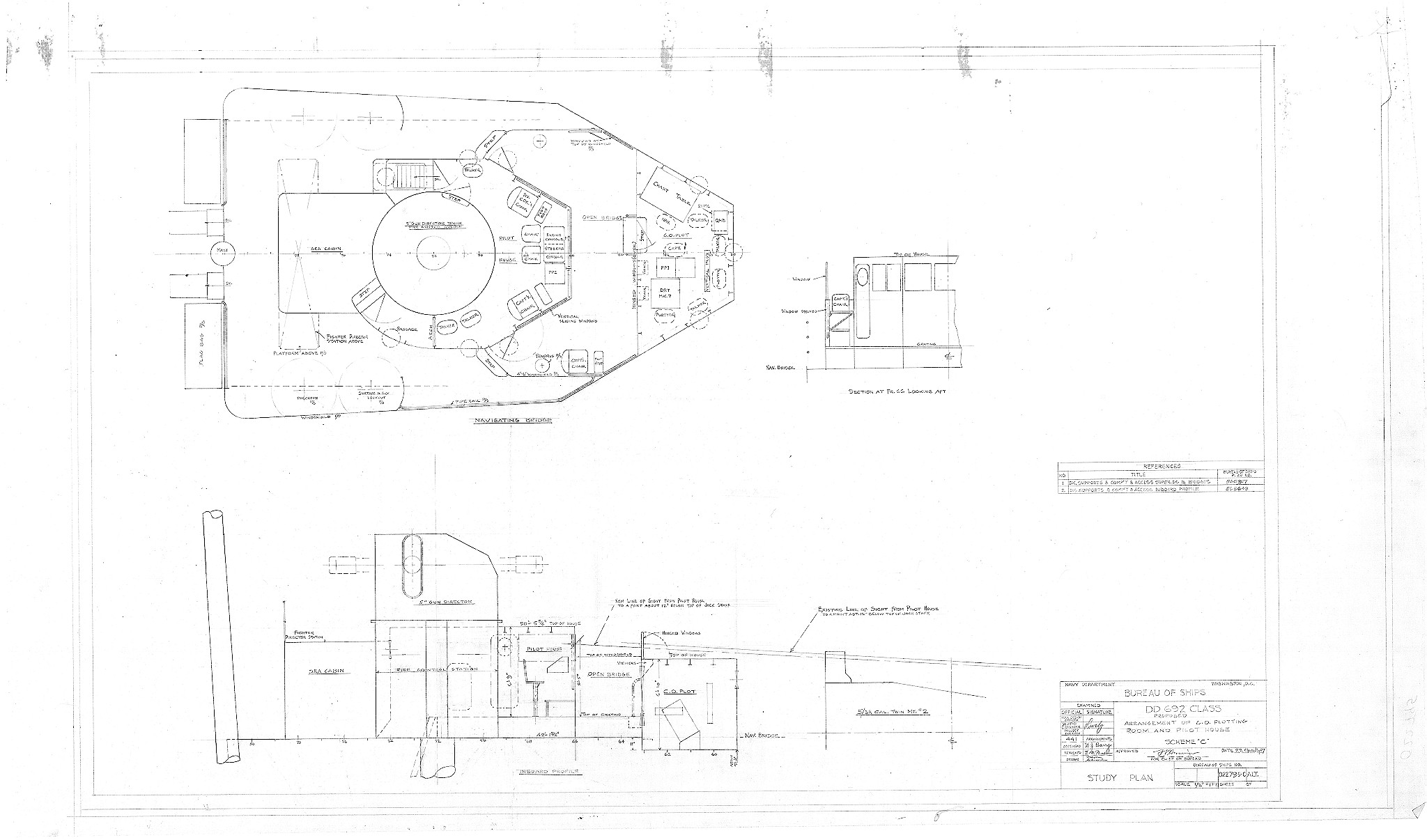
| These four
plans give you an idea of the number of times that the plans were drawn
and redrawn before becoming the "official" Plan. These represent the schemes for the C.O. Plotting Room and Pilot House. |
|
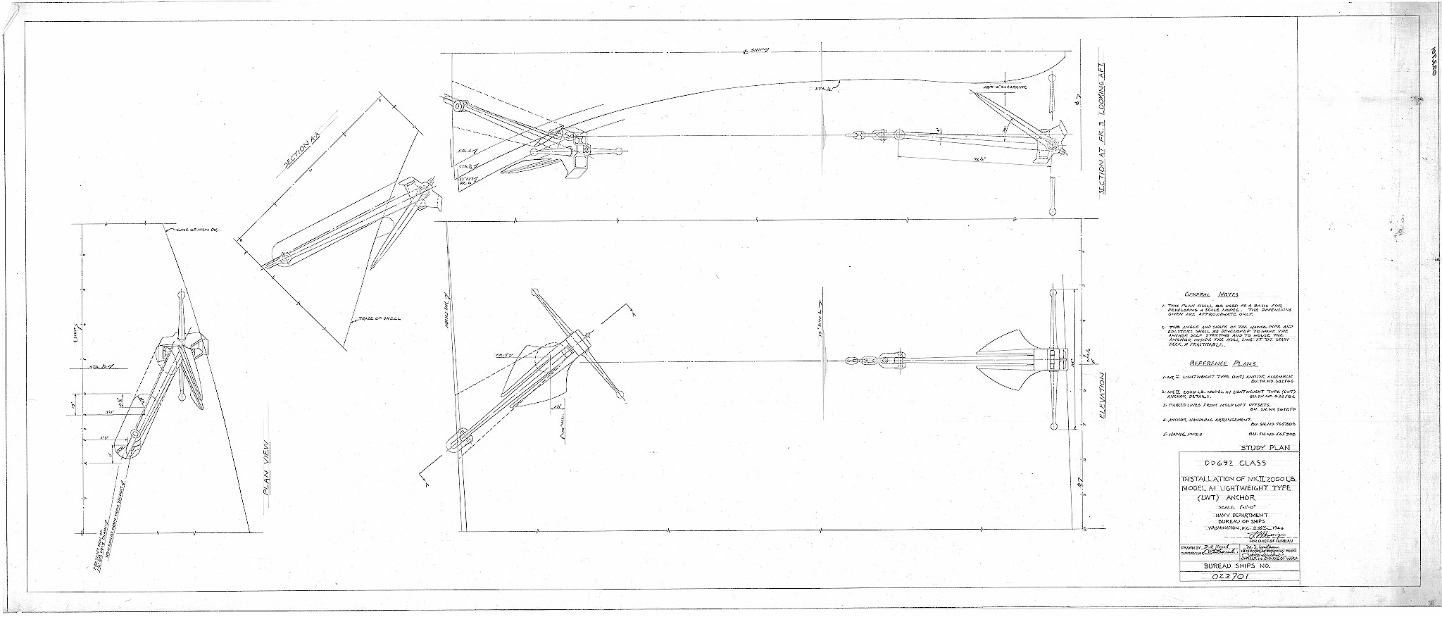
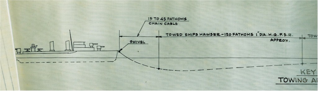
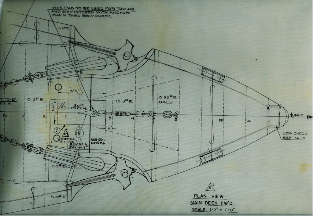
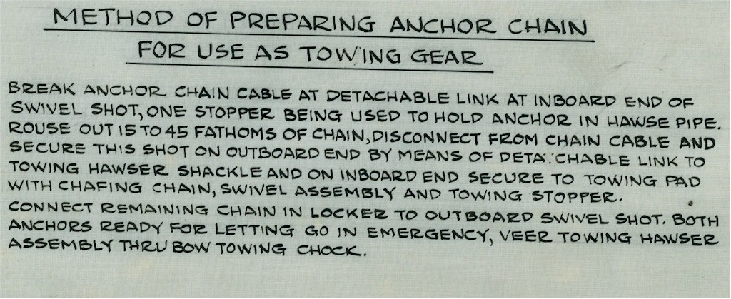
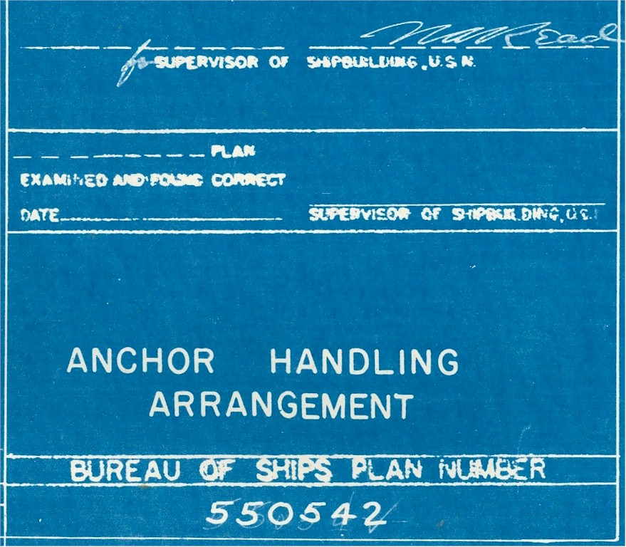
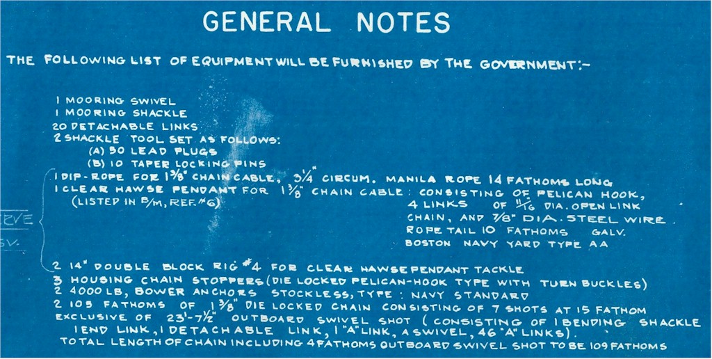
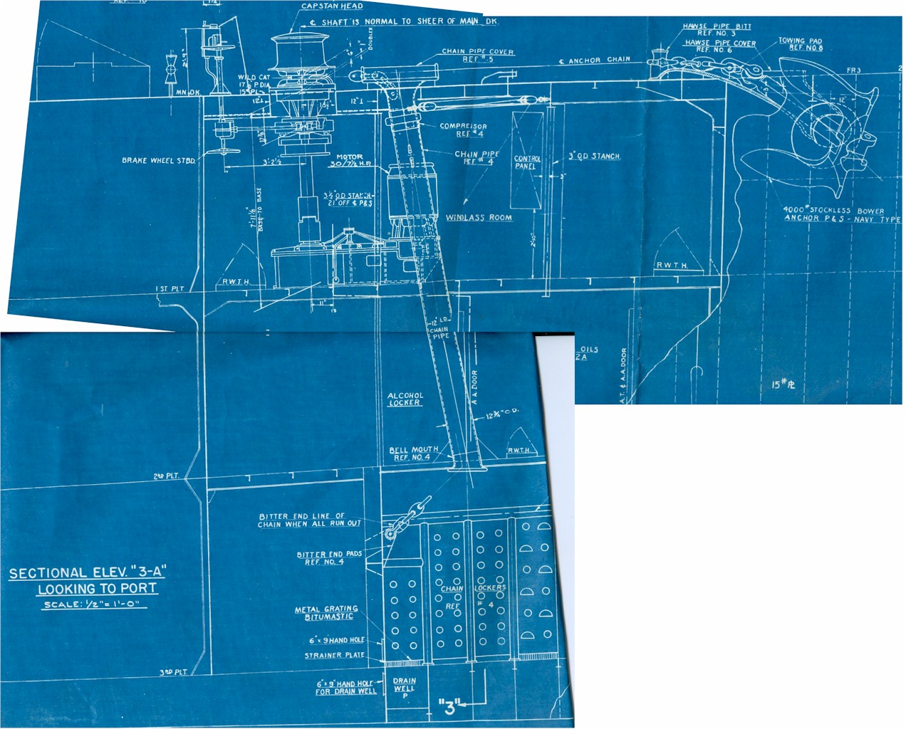
Plans for installation of a lightweight anchor
 |
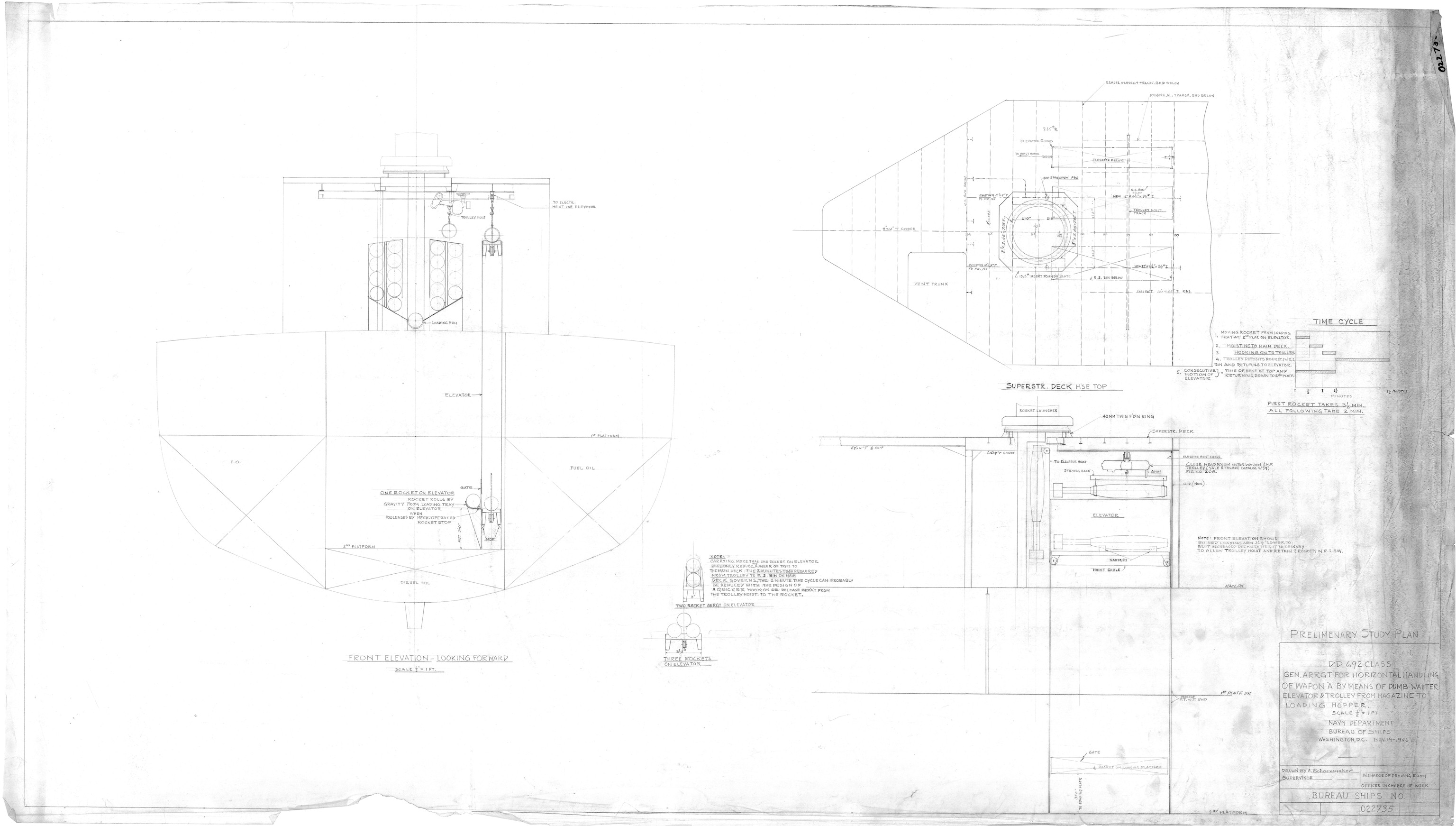 |
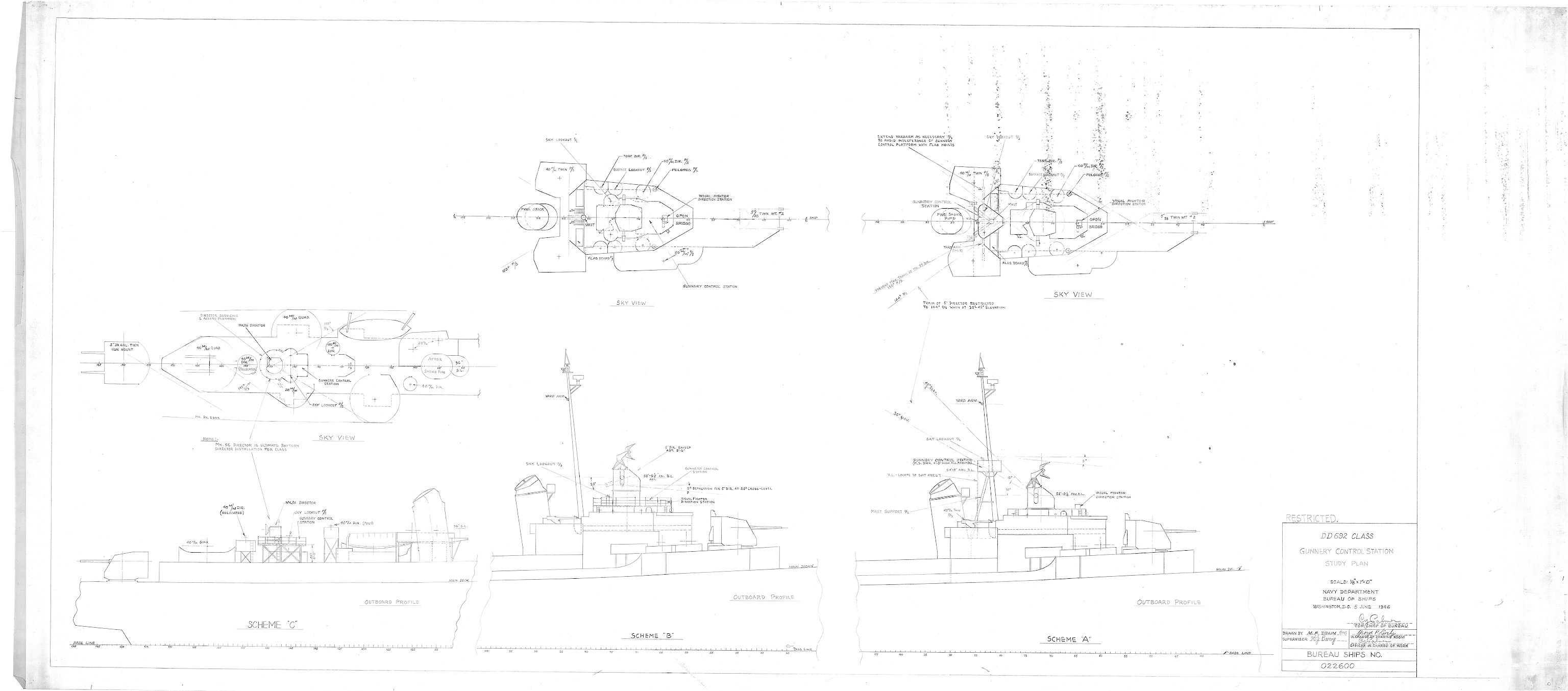
| Plans for the Gunnery Control Station | Plans for handling of the Wapon 'A' |
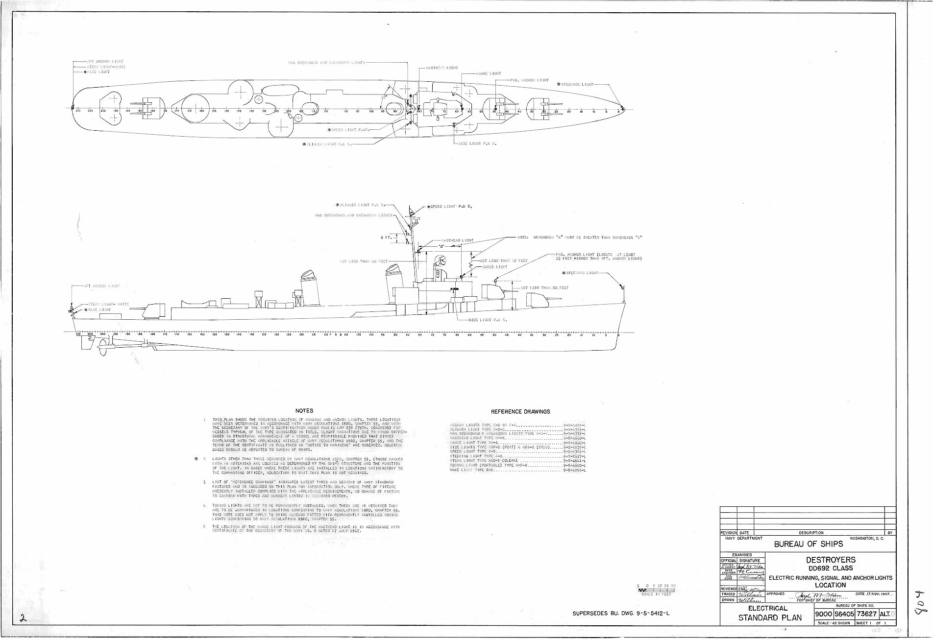
1947 BuShips DD-692 Class Electrical
Running, Signal & Anchor Lights
BuShips - November 17, 1947
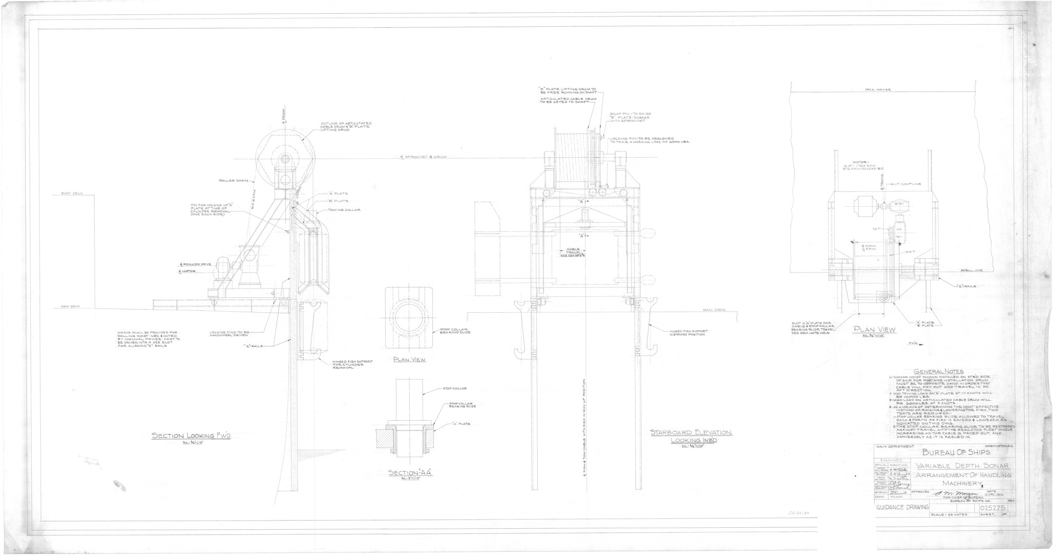
1950 BuShips Variable Depth
Sonar Installation
BuShips - December 12, 1950
1951 BuShips Grebe Missile
System (XSUM-N-2) Installation
BuShips - March 10, 1951
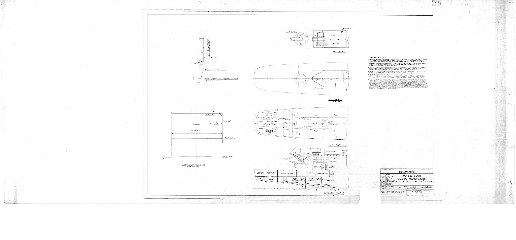
The Grebe was part of the Kingfisher family of guided anti-ship/anti-submarine weapons, which was developed under the prime contract of the National Bureau of Standards (NBS). Originally projected as Kingfisher E in 1946, it was subcontracted to Goodyear, and redesignated in September 1947 as SUM-2 (SUM-N-2 from early 1948) Grebe. Grebe was the only ship-launched missile in the Kingfisher family, the others (including the AUM-N-2 Petrel (Kingfisher C), AUM-N-4 Diver (Kingfisher D) and AUM-N-6 Puffin (Kingfisher F)) all being air-launched. The Kingfisher E specification in 1946 called for a subsonic rocket-boosted heavy MK 35 torpedo, which was to be launched from surface ships. By 1948, the payload had been changed to a lighter MK 41 torpedo, and a long-range version with a pulsejet sustainer propulsion was also planned. The SUM-N-2 was launched in the direction of a sonar-detected target, and after a preset distance, it began its terminal dive to release its homing torpedo. Grebe was mainly intended for use against deep-diving submarines. Twenty XSUM-N-2 prototypes were built, and flight-tested around 1950. Grebe never became operational, reportedly because none of the then existing sonars could match the missile's range. However, the date of termination of the SUM-N-2 program is unclear.
1951 BuShips DD-692 Class
Ship Stabilizer Installation
BuShips - March 30, 1951
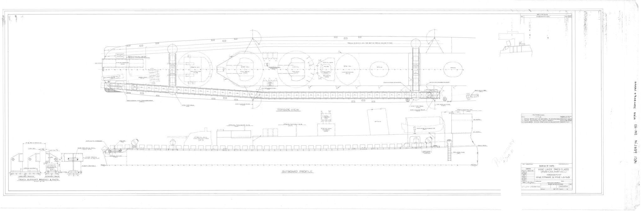
1951 BuShips DD-692 Class
DM23 Conversion
BuShips - September 4, 1951

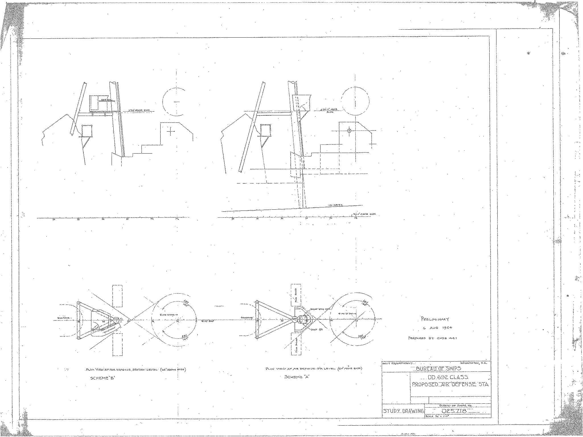
1954 BuShips Proposed Air
Defense Station
BuShips - August 6, 1954
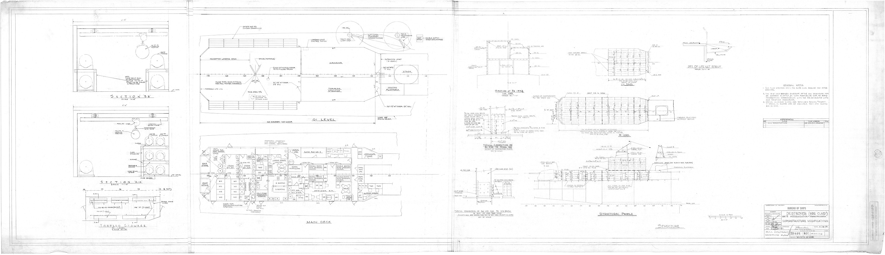
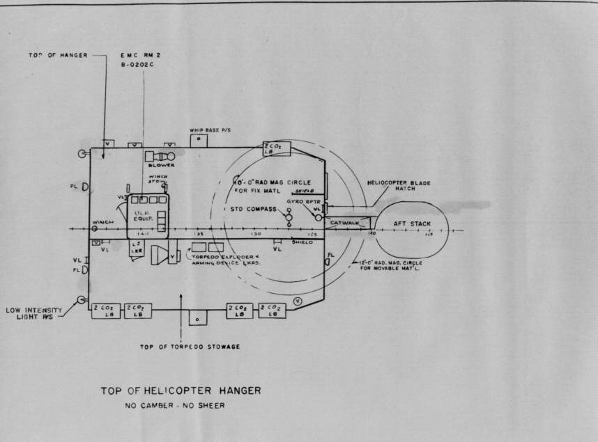
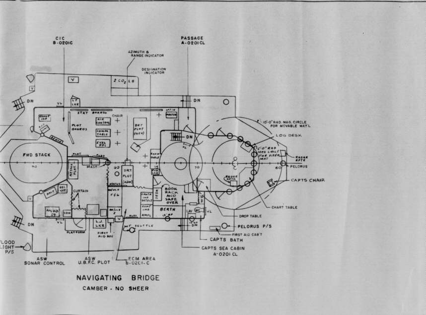
1959's FRAM II
Superstructure Modification Plans
BuShips - April 29, 1959
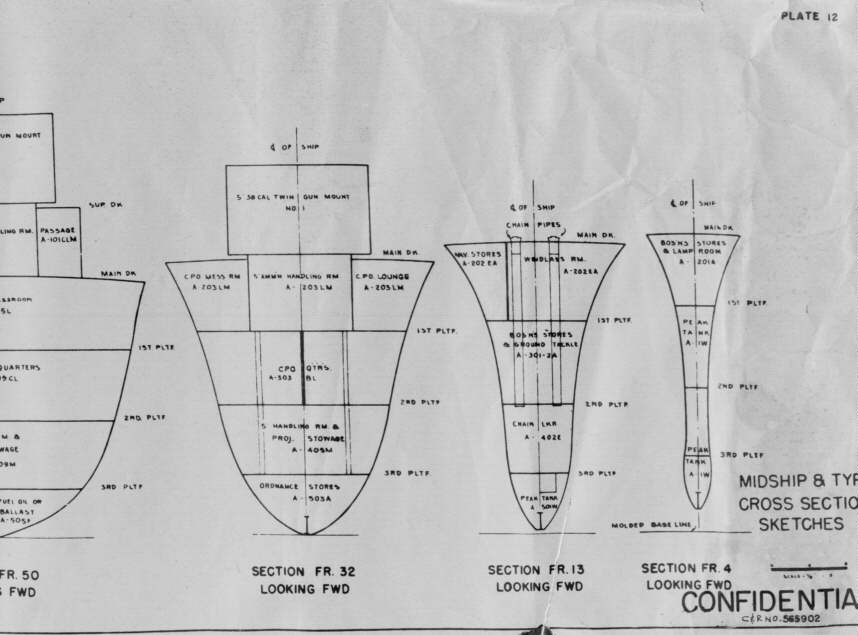
1960's FRAM II Deck, Cross
Section & Starboard View Plans
Paulson Engineering Service, Charleston -
November 24, 1961
Bridge Level |
||||
 |
 |
 |
||
|
||||
 |
 |
 |
||
|
||||
 |
 |
 |
 |
 |
|
||||
 |
 |
 |
 |
 |
| Second Platform Level |
||||
 |
 |
 |
 |
|
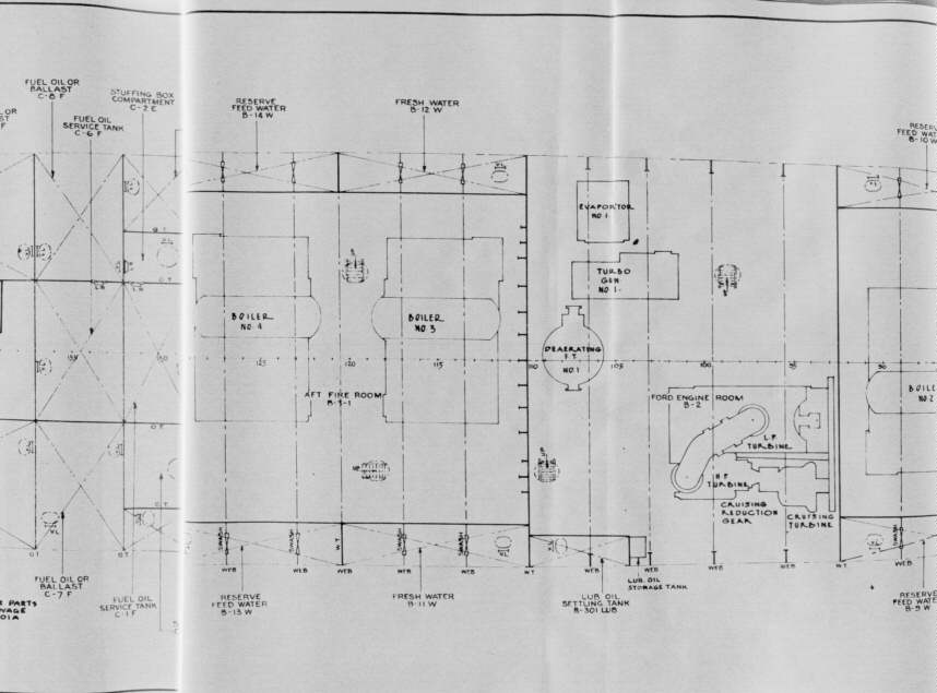
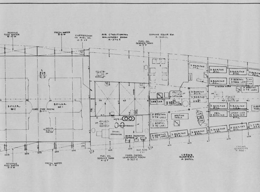
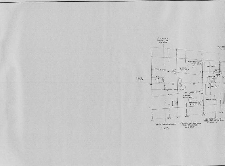
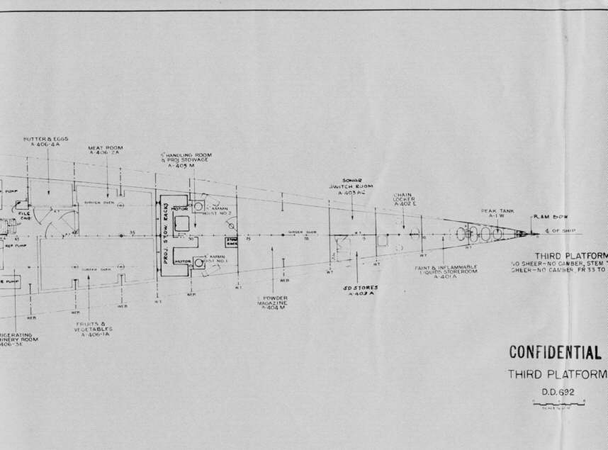
| Third Platform Level |
||||
 |
 |
|||
| Hull Platform |
||||
 |
 |
 |
 |
|
| Cross Section Views |
||||
 |
 |
 |
 |
 |
| Starboard Profile Sketch |
||||
 |
 |
 |
||
A Sincere Thank You to Chuck Morrell who let us borrow the FRAM II plans for scanning
1968 Charleston Naval
Shipyard Overhaul Plans
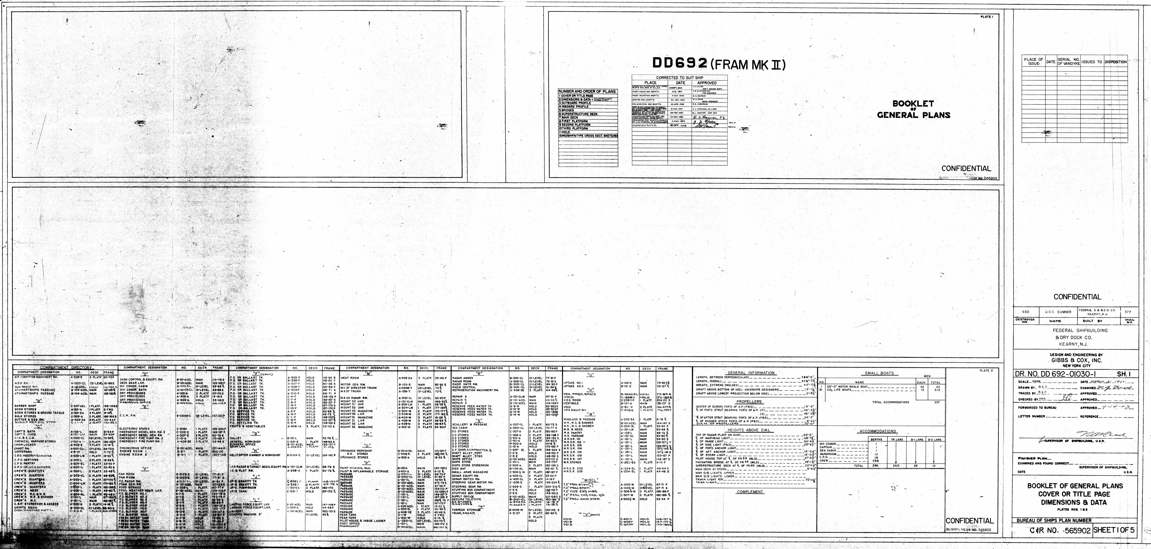
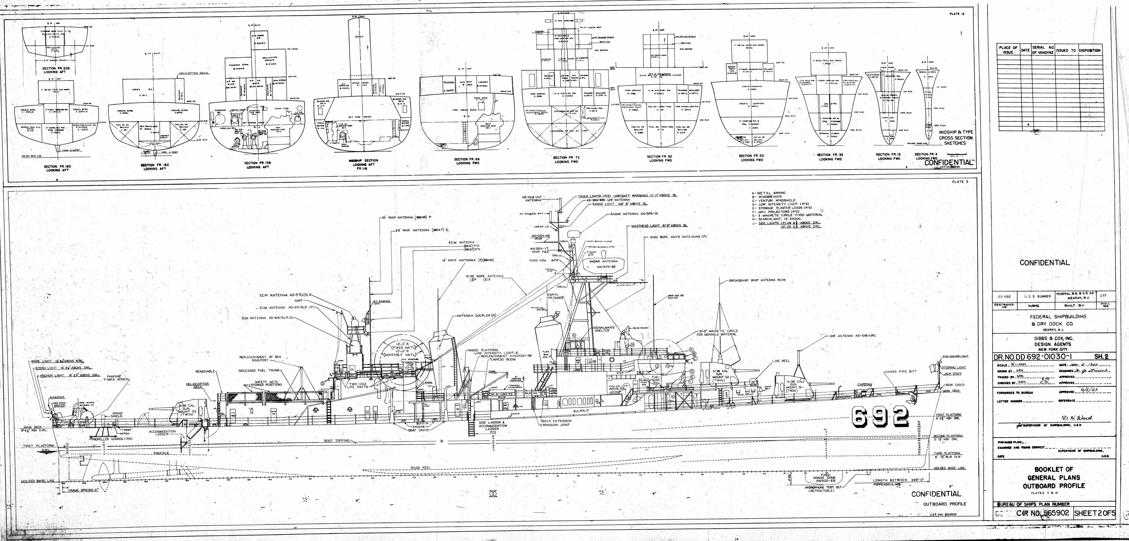
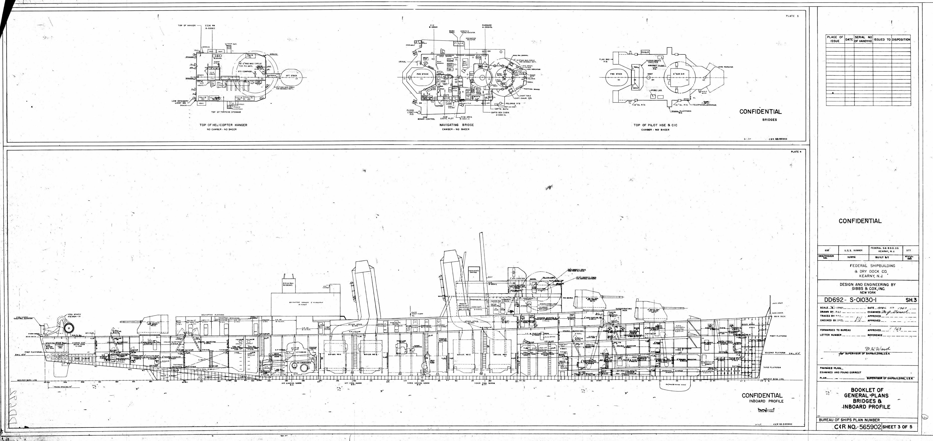
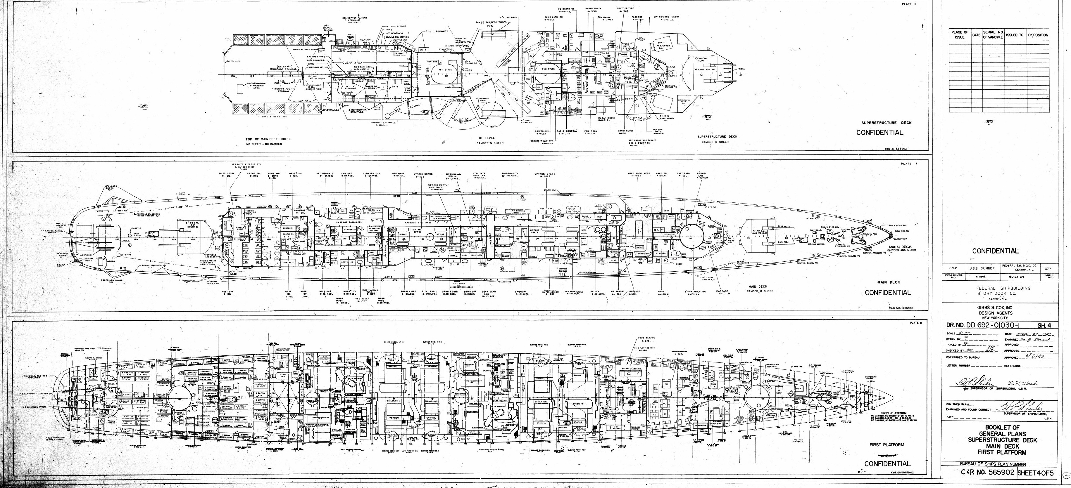
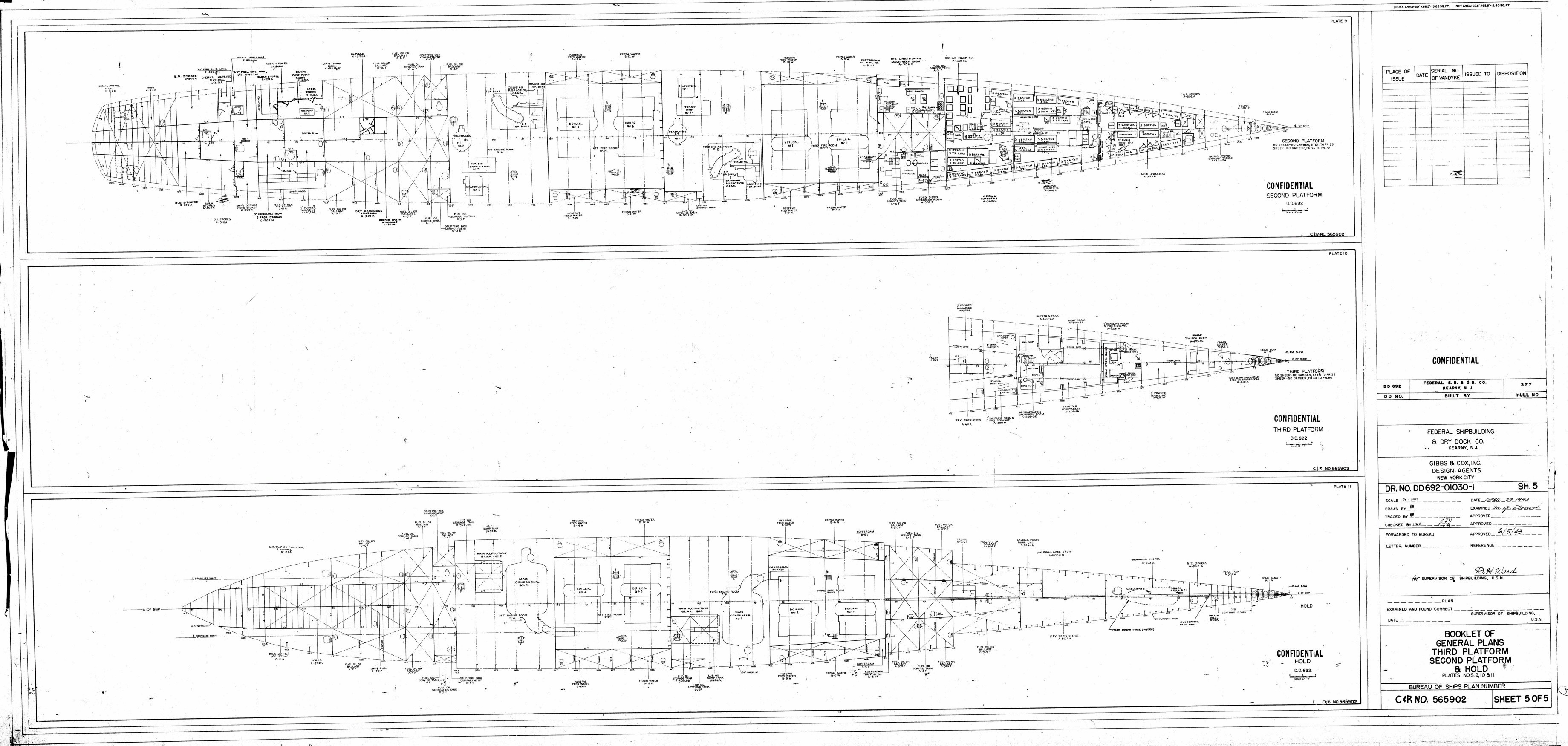
Booklet of General Plans
October 18, 1968
|
|
|
|
Cover/Title Page with
Dimensions & Data |
|
|
|
|
|
Outboard and Cross Section Profiles |
Bridges & Inboard Profile |
|
|
|
|
Superstructure, Main Deck and
First Platform |
Second, Third and Hold
Platforms |
Many thanks to Ed Raney of the USS Willard Keith (DD-775) who supplied us with this set of plans from the 1968 Charleston Navy Yard overhaul.
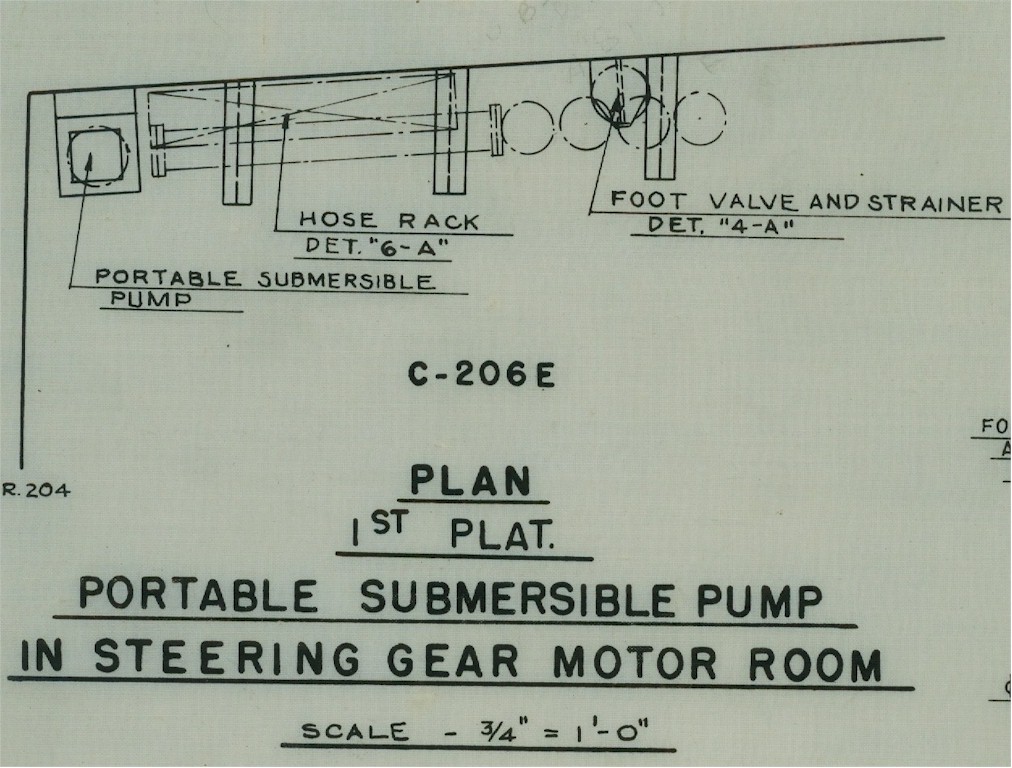
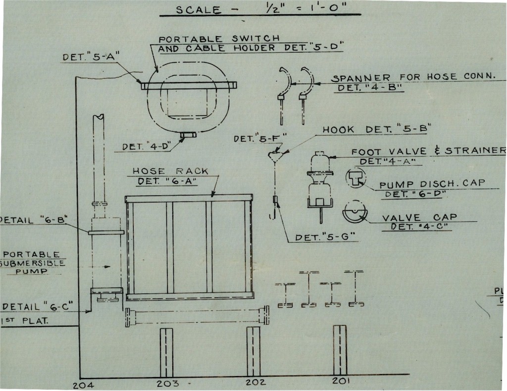
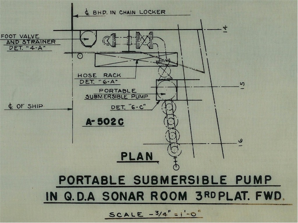
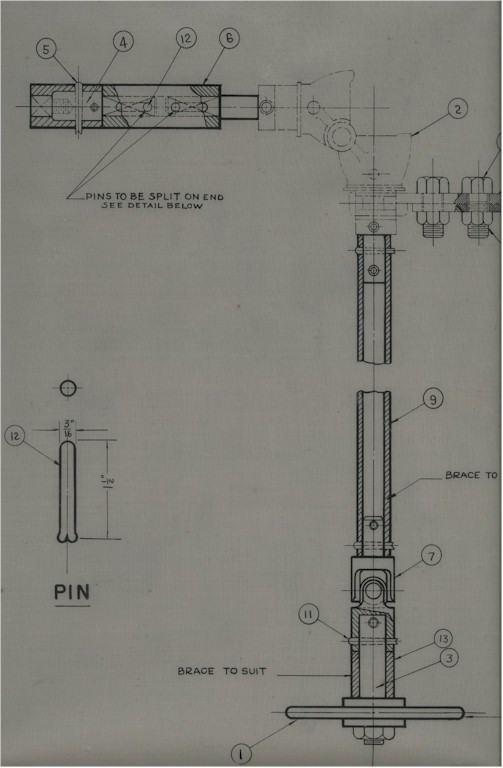
Odd's & End's Shipyard Plans
The shipyards created plans for everything that
went aboard and special operations,
these plans, thanks to Ed Zajkowski, display examples of this detail work.
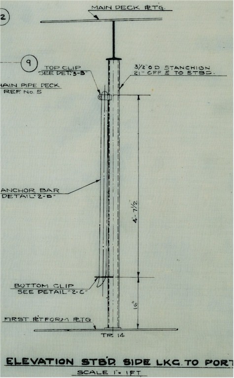
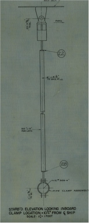
Plans for the ANCHOR BAR which was stored in the Bos'ns Locker.
 |
 |
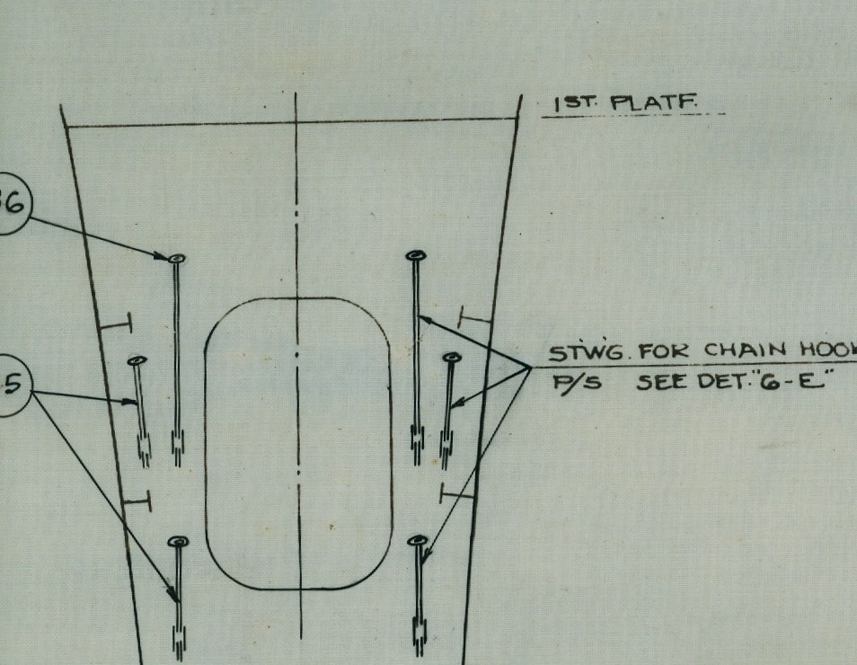
Plans for the CHAIN HOOKS in the Bos'ns Locker at Frame 8 |
|
 |
 |
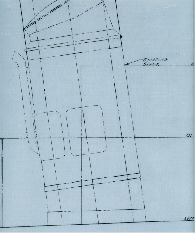
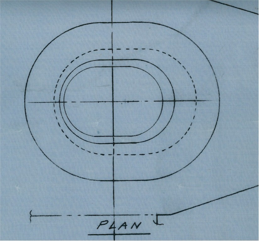
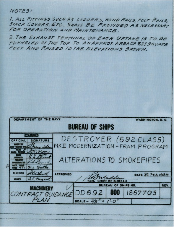
Plans for alterations to the SMOKEPIPES during FRAM from 1959 |
|
|
|
 |
||
 |
 |
 |
|
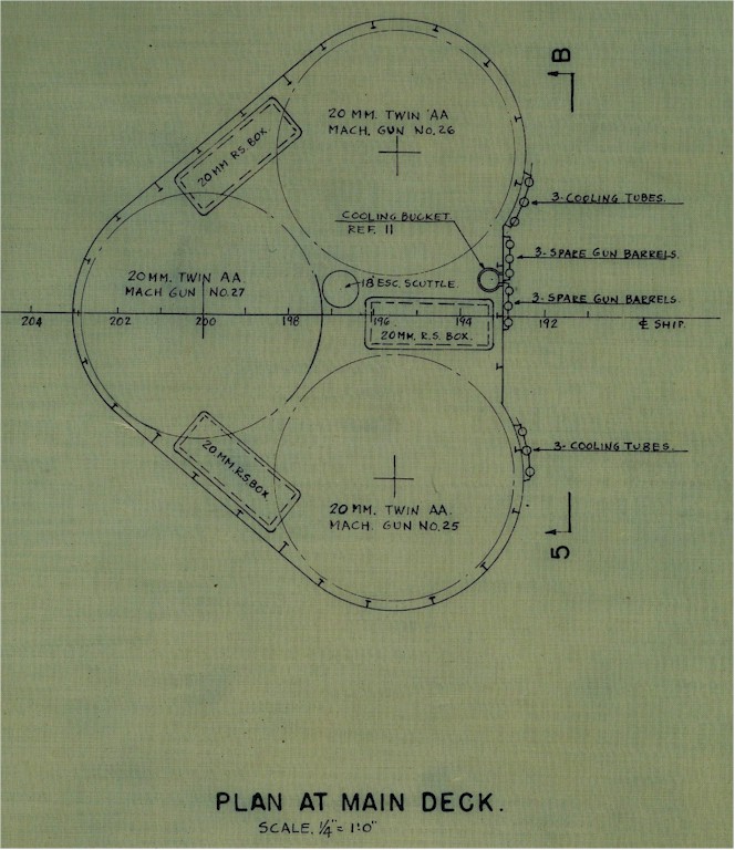
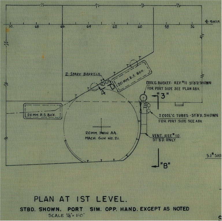
Plans for the 20MM GUNS, location and supporting equipment |
||
 |
 |
 |
 |
||
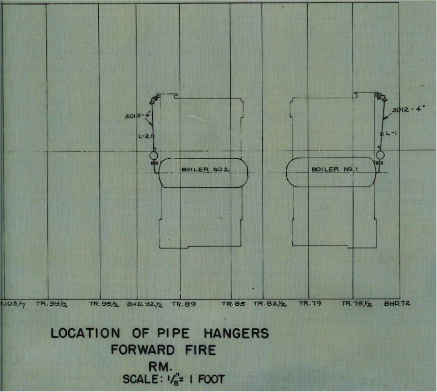
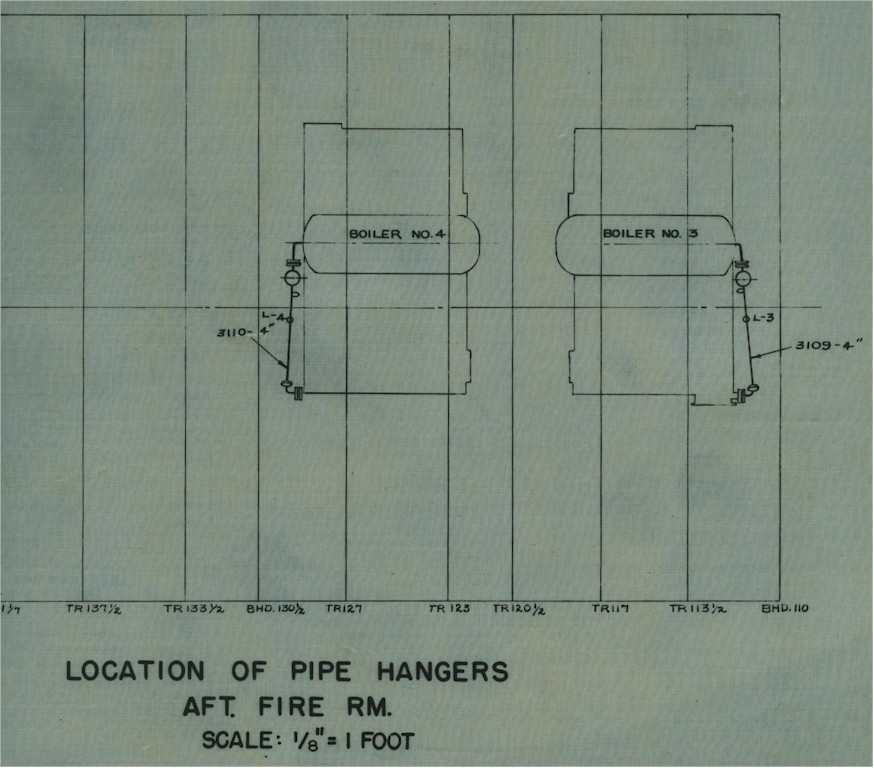
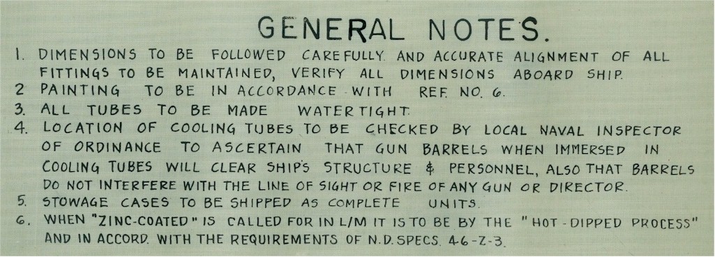
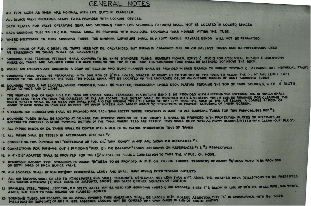
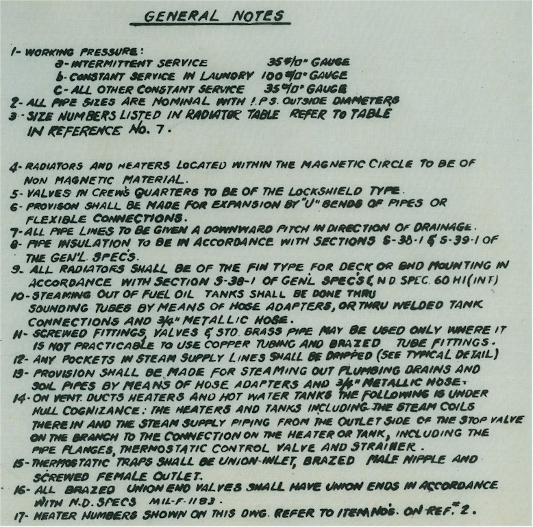
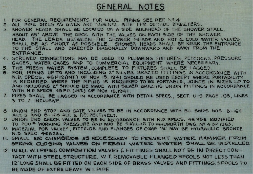
Plan NOTES for BT's, the Oil King and other engineers |
||
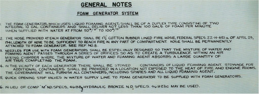
Plan
NOTES for the Fire Extinguishing Systems
 |
 |
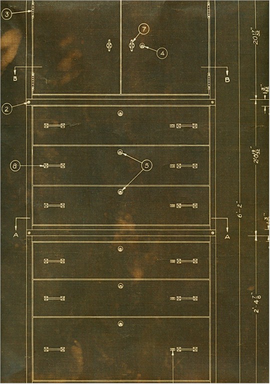
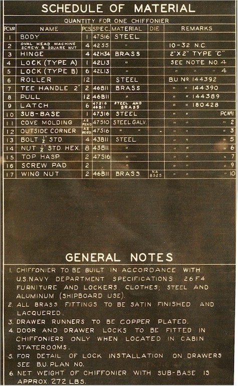
From Officer's Country - Plans for their CHIFFONIER 36" WITH LOCKER STEEL 1942 |
|
 |
 |
 |
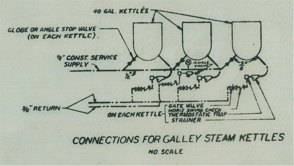
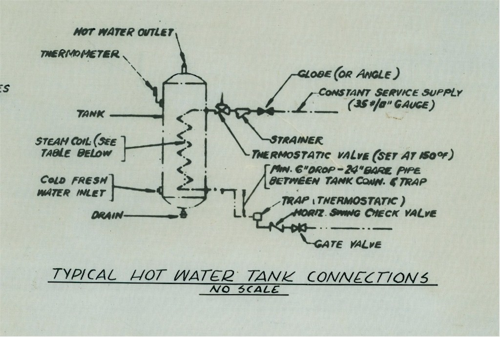
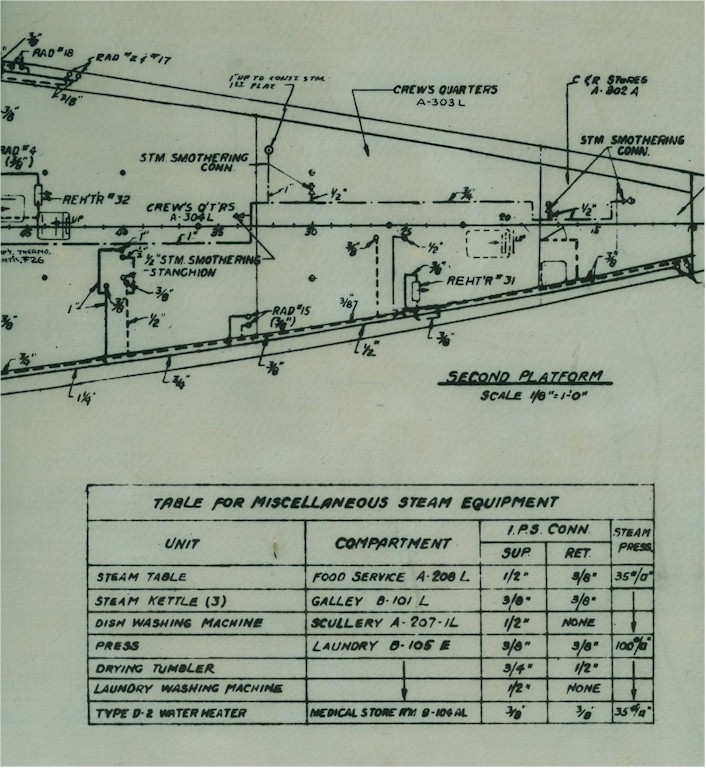
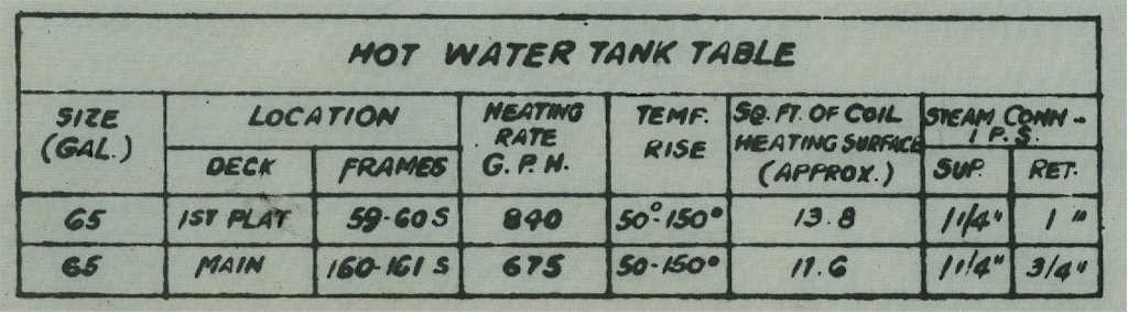
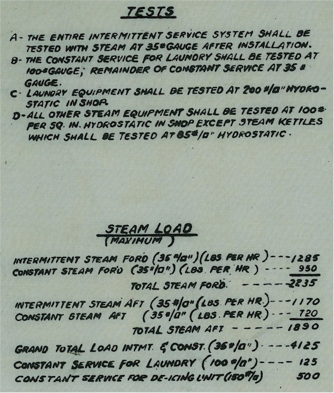
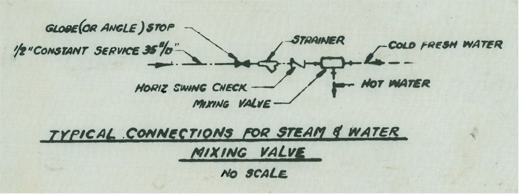
| Plans and notes for the AUXILIARY STEAM SYSTEM |
||
 |
 |
 |
 |
 |
 |
 |
 |
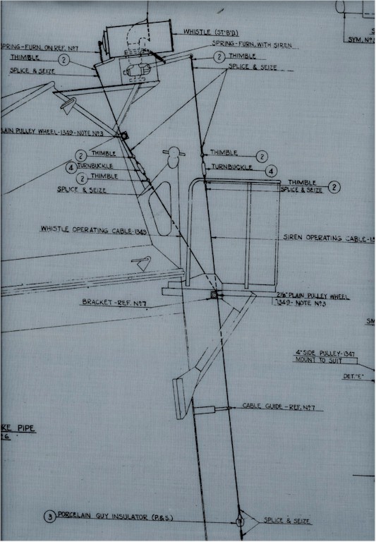
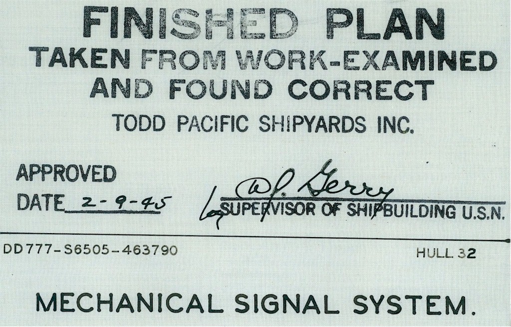
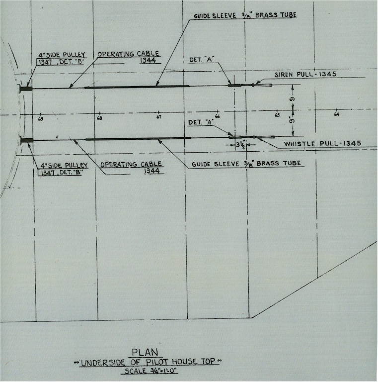
Plans for the SHIP'S WHISTLE and SIREN PULLS |
|||
 |
 |
 |
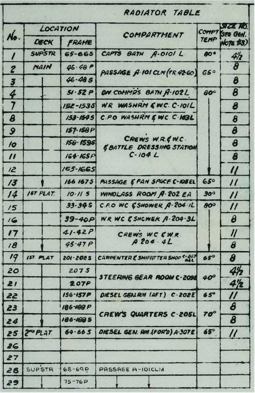
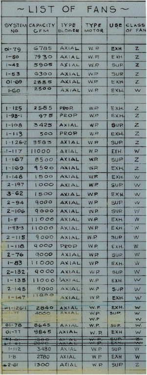
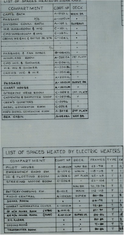
Listings of installed FANS and HEATERS |
||
 |
 |
 |
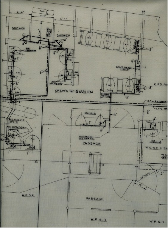
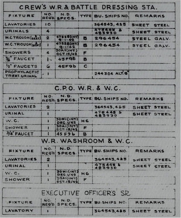
Plans for the FORWARD CREW'S HEAD |
||
 |
 |
 |
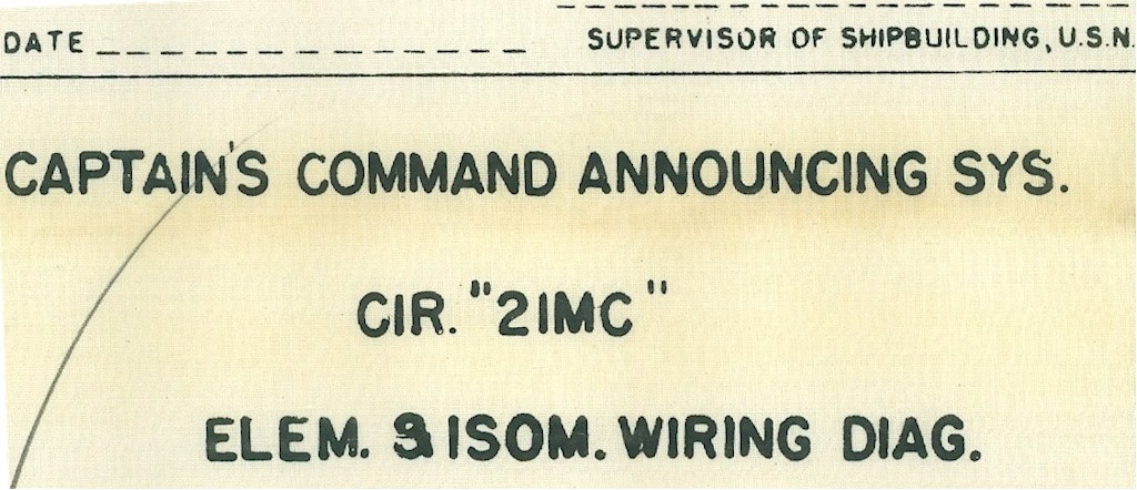
NOTES for the CAPTAIN'S COMMAND ANNOUNCING CIRCUIT 21MC |
||
 |
 |
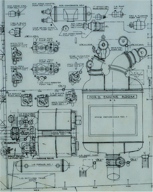
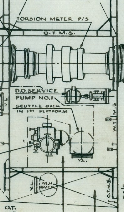
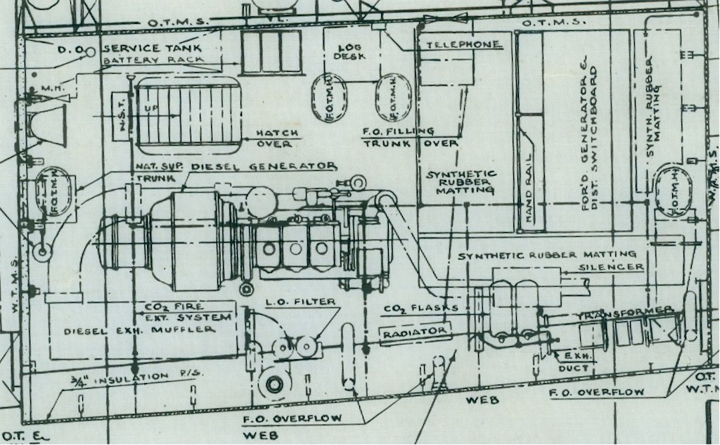
Plans for the location of Main Machinery Forward |
|
 |
 |
 |
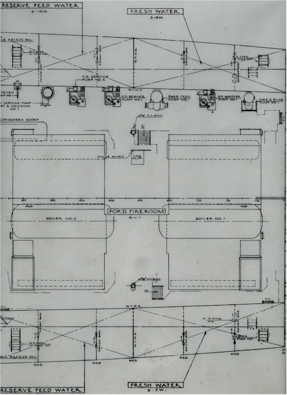 |
| Main machinery on the lower level of the Forward Engine Room, lower level | Starboard Shaft Alley | Forward Diesel | Pump row in the Forward Fire Room, lower level |
|
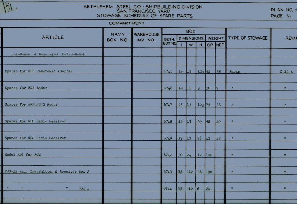
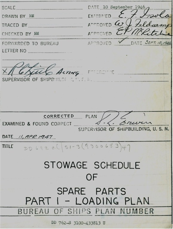
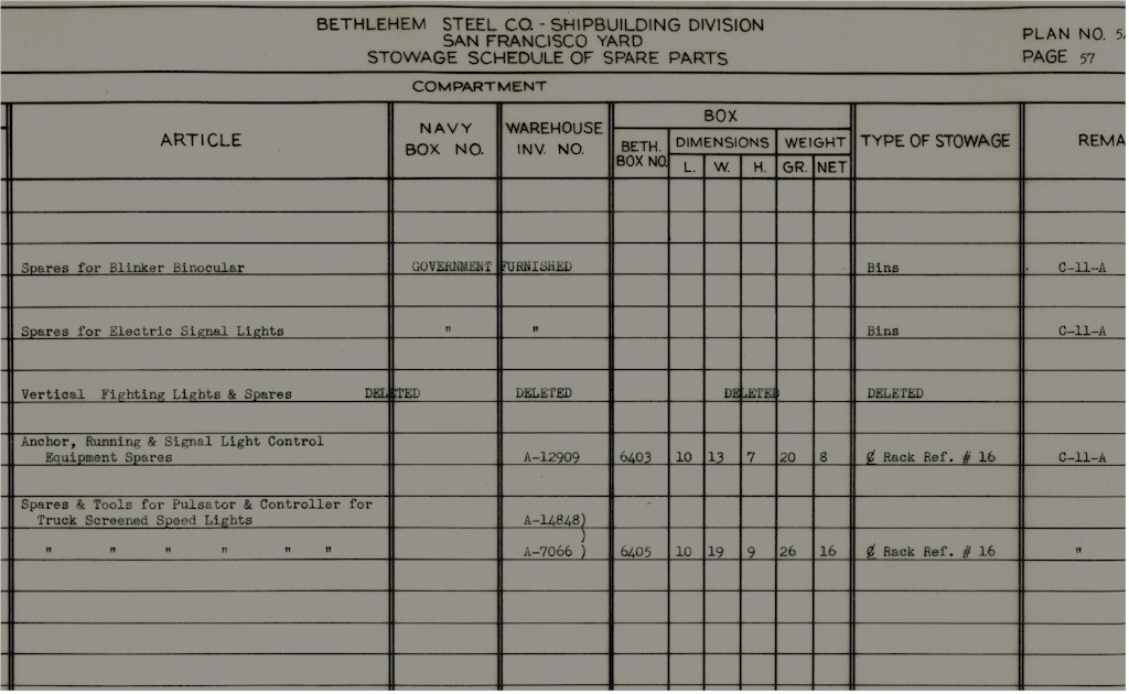
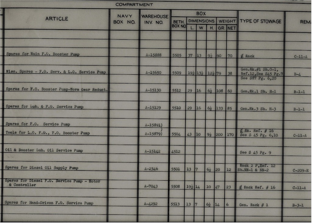
Shipyard LOADING PLAN for stowage of Spare Parts This one is for the USS Henley but would be very close to the Sumner's |
|||
 |
 |
 |
|
 |
 |
 |
 |
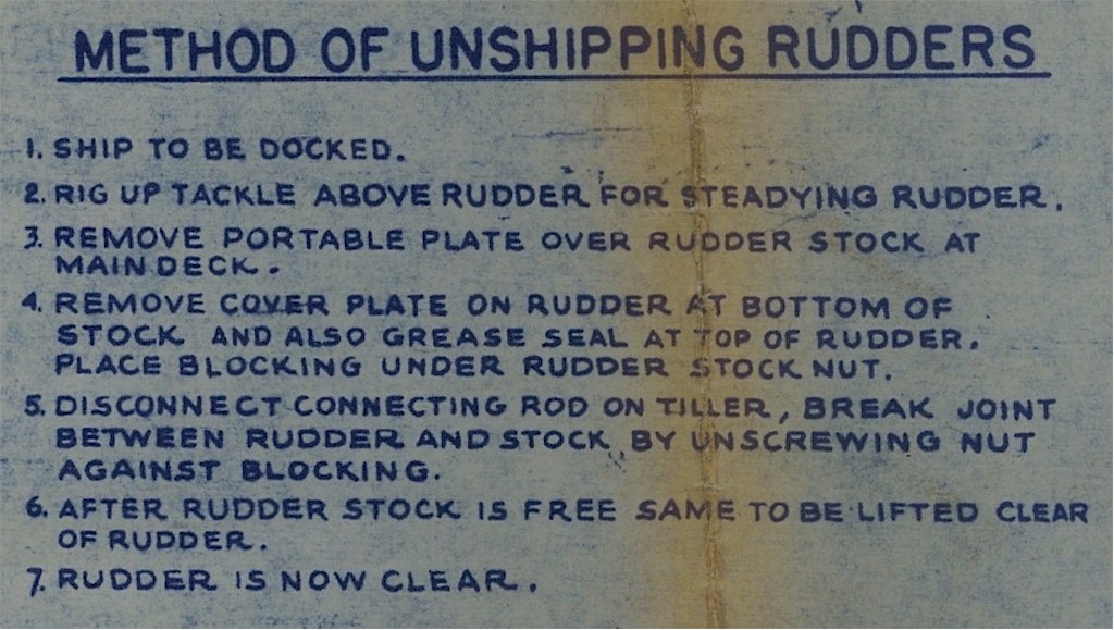
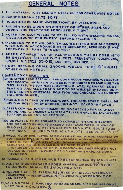
Plan for the RUDDERS |
|||
 |
|
 |
 |
 |
|
|
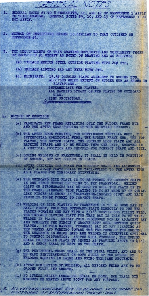
Modified Plans for the RUDDERS 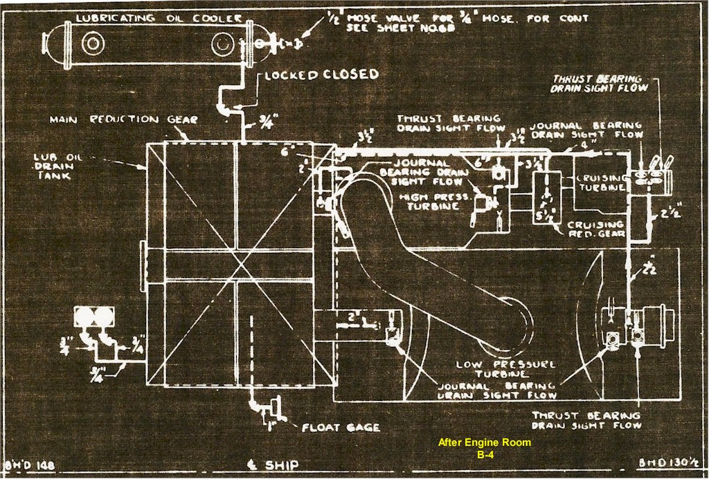 |
|
 |
|
 |
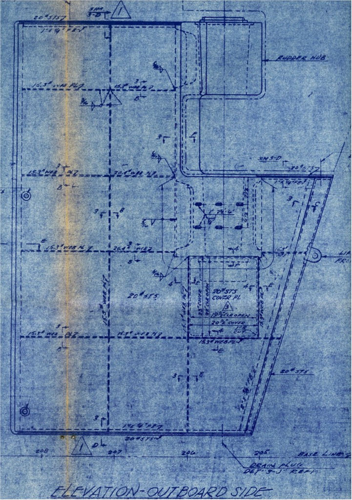 |
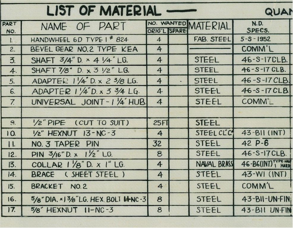
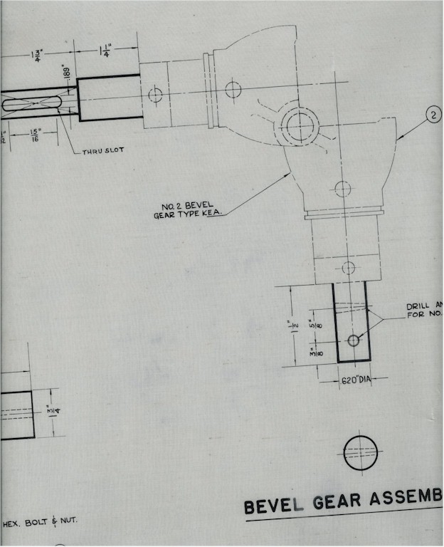
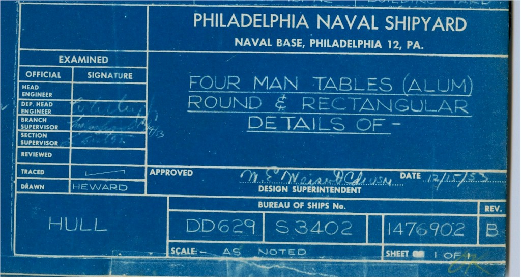
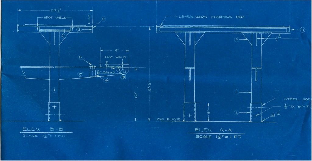
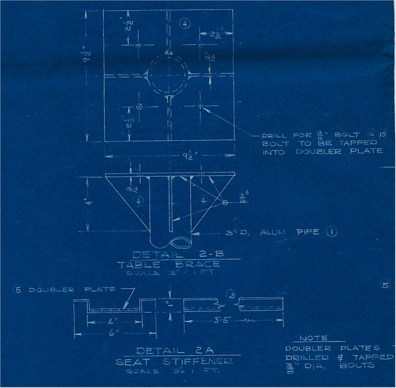
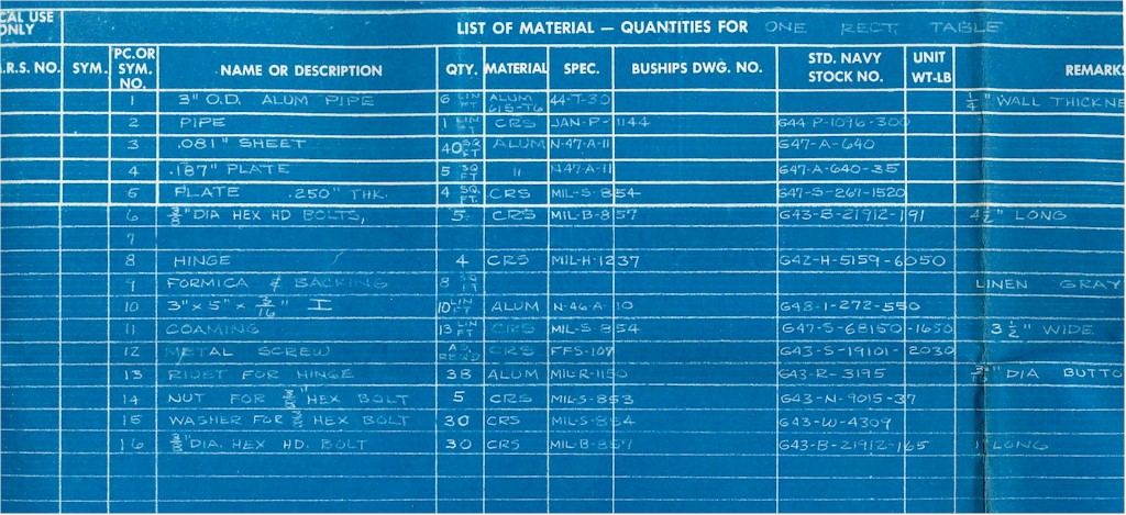
Plans and parts list for a Mess Deck table.
 |
 |
 |
 |
 |
|
 |
 |
 |
|
|
|
|
Docking Plan
Gibbs & Cox - September 11, 1943
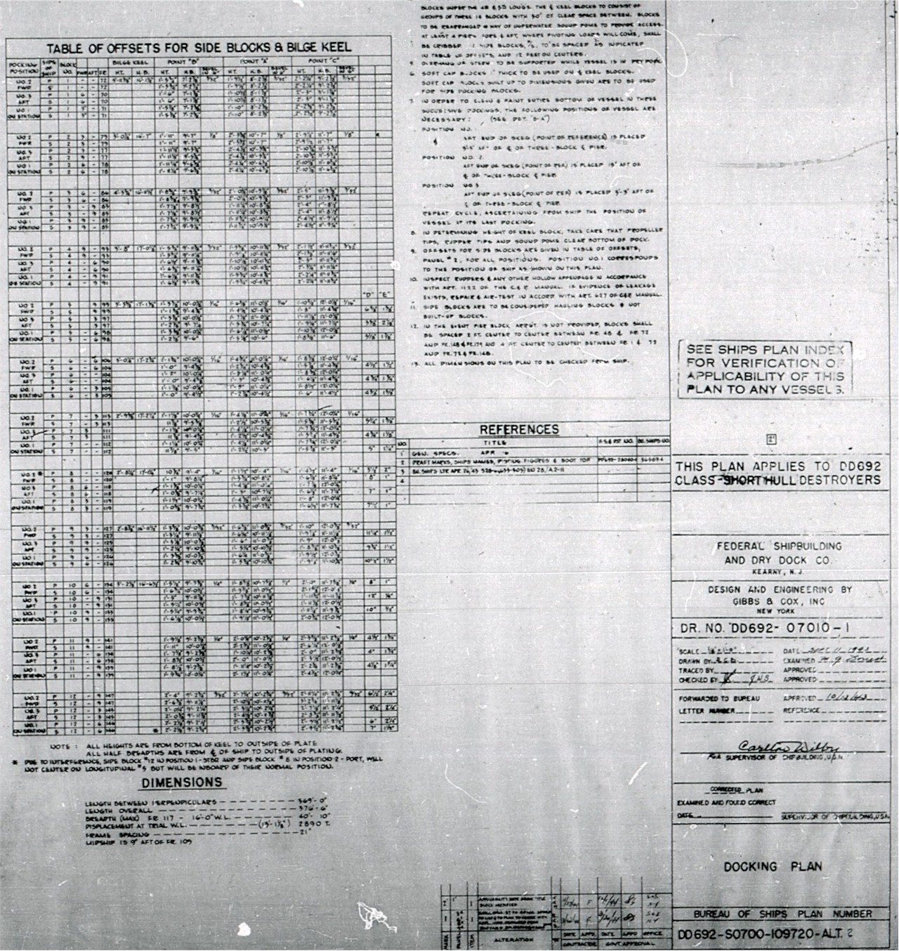
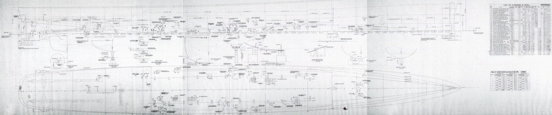
These two plan pages show the amount of detail and
planning that went into the construction of a destroyer.
Each block is
displayed, showing where it went and it's exact dimensions!
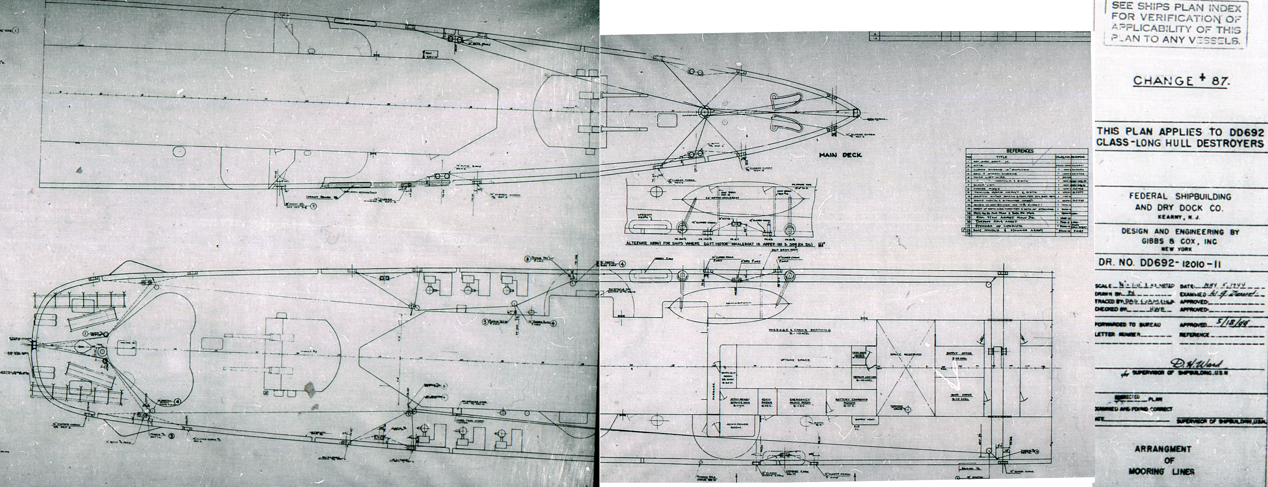
Mooring Lines
Gibbs & Cox - May 5, 1944
The Ship's Bell
Gibbs & Cox - May 14, 1943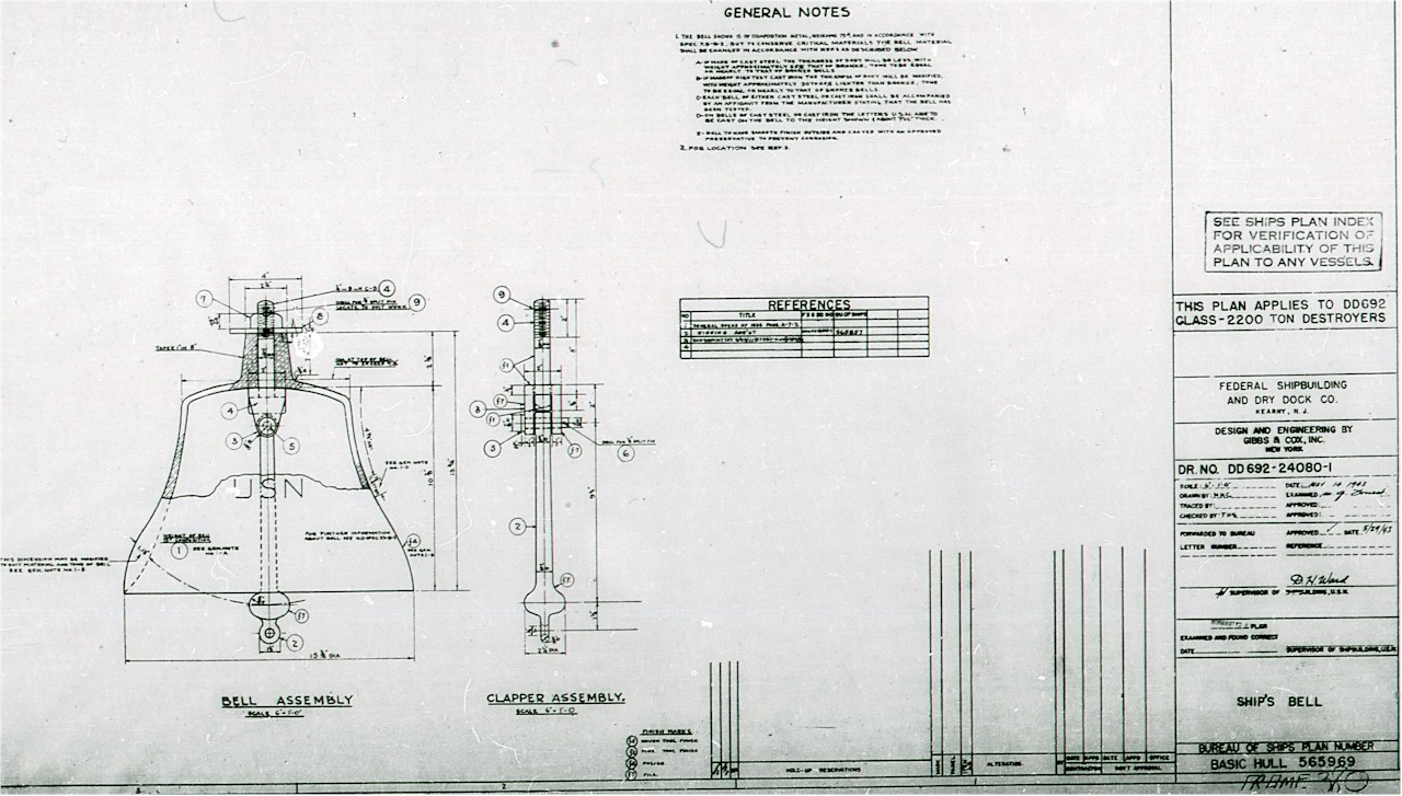
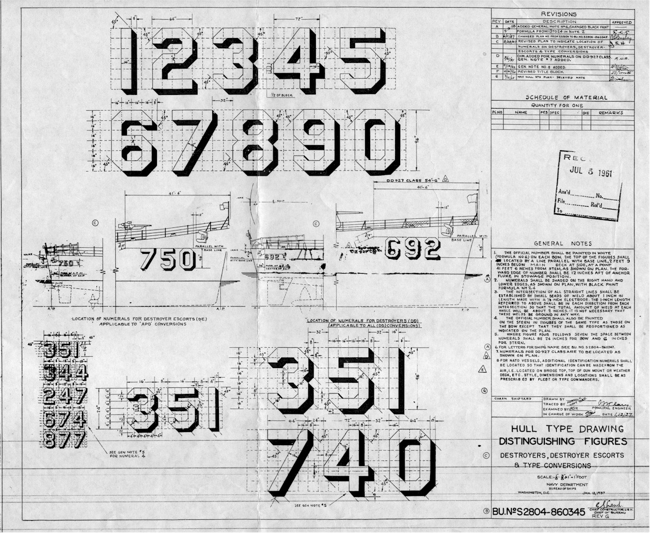
How to paint those bow and fantail HULL NUMBERS thanks to Jon Barrett of Navy Yard Associates.
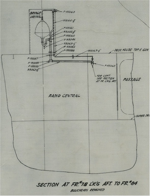
And of course, plans for the BRIDGE URINAL which was gold plated!
Ed Zajkowski has many plans from 1944 and 1945 along with corresponding photos
of the interior of Sumner Class Destroyers on NavSource at page
http://www.navsource.org/archives/05/interior.htm.
It is a big page but well worth the visit.